Transcription of 16-Bit, Six-Channel, Simultaneous Sampling Analog …
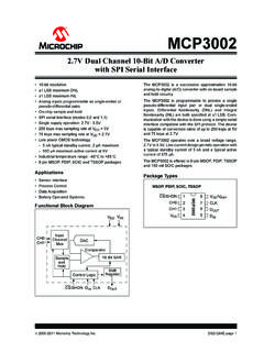
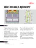
1 94929088868482807876747270 Signal-to-Noise Ratio (dB)-40-25-10520355065125 Temperature ( C) 8095 110 AVDD = BVDD = 5 VHVSS = 15V, HVDD = 15Vf= 10kHz, f= MaxRange = 4 VInternal Reference- SIGNALDATAREFSAR /WRRESETENSTBYCSRD/DB[15:0]WORD/BYTEPAR/ SERFSCH_A0 CONVST_AAGNDREFC_AREF_IOAVDDBVDDBGNDAGND HVDDHVSSC ontrolLogicConfigRegisterI/OSAR ADCCH_A1 AGNDSAR ADCCH_B0 CONVST_BAGNDREFC_BSAR ADCCH_B1 AGNDSAR ADCCH_C0 CONVST_CAGNDREFC_CSAR ADCCH_C1 AGNDC lockGeneratorProductFolderSample &BuyTechnicalDocumentsTools &SoftwareSupport &CommunityReferenceDesignAn IMPORTANTNOTICEat the end of this datasheetaddressesavailability,warranty, changes,use in safety-criticalapplications.
2 Intellectualpropertymattersand DECEMBER2010 REVISEDFEBRUARY2016 ADS855516-Bit, Six-Channel, SimultaneousSa mplingAnalog-to-DigitalConverter11 Features1 Six SARADCsGroupedin ThreePairs MaximumDataRatePer ChannelWithInternalClockand Reference:630 kSPS(Parallel)or 450 kSPS(Serial) MaximumDataRatePer ChannelWithExternalClockand Reference:800 kSPS(Parallel)or 500 kSPS(Serial) Pin-Selectableor ProgrammableInputVoltageRanges:Up to 12 V ExcellentAC , 94-dBTHD Programmableand V to V and V to 3 V ComprehensivePower-DownModes: DeepPowerDown(StandbyMode) Auto-NapPowerDown SelectableParallelor SerialInterface OperatingTemperatureRange.
3 40 C to 125 C LQFP-64 Package2 Applications PowerQualityMeasurements ProtectionRelays Multi-AxisMotorControls ProgrammableLogicControllers IndustrialDataAcquisitionSNRvs Temperature3 DescriptionThe ADS8555devicecontainssix low-power, 16-Bit, successiveapproximation register(SAR)-basedanalog-to-digitalconv erters(ADCs)withtrue up to630kSPSin parallelinterfacemodeor up to450kSPSif the serialinterfaceis the parallelinterfacecan be set to eightor 16bits. In serialmode,up to threeoutputchannelscanbe ADS8555deviceis specifiedoverthe extendedindustrialtemperaturerangeof 40 C to 125 C and isavailablein an (1)PARTNUMBERPACKAGEBODYSIZE(NOM)ADS8555 LQFP(64) (1) For all availablepackages,see the orderableaddendumatthe end of the DECEMBER2010 :ADS8555 SubmitDocumentationFeedbackCopyright 2010 2016,TexasInstrumentsIncorporatedTableof Contents1 Pin Configurationand (ReadAccess).
4 (WriteAccess).. Applicationsand Deviceand Mechanical,Packaging,and RevisionHistoryNOTE:Pagenumbersfor previousrevisionsmay differfrompagenumbersin the (October2015)to RevisionDPage ChangedFigure36: changedcapacitorvaluesfrom820 nF to 820 pF ..32 ChangesfromRevisionB (February2011)to RevisionCPage AddedESDR atingstable,FeatureDescriptionsection,De viceFunctionalModes,Applicationand Implementationsection,PowerSupplyRecomme ndationssection,Layoutsection,Deviceand DocumentationSupportsection,andMechanica l,Packaging,and (January2011)to RevisionBPage Changeddescriptionof pin 18 in Pin Addedclarificationof INT Changedbit C20 in (December2010)
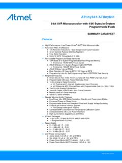
5 To RevisionAPage Changeddescriptionof CONVST_C,CONVST_B,and CONVST_Apins in Pin Changedfirst /DCENENDB6/SCLKDB5/DCIN_ADB4/DCIN_BDB3/D CIN_CDB2/SEL_CDB1/SEL_BDB15DB0/SEL_AREF /WRENBUSY/INTHW/SWCS FS/PAR/SERRDAVDDCONVST_CAGNDCONVST_BREFC _CCONVST_AAGNDSTBYREFC_BAGNDAGNDAVDDREFC _ARANGE/XCLKAGNDRESETAGNDWORD/BYTEREFIOH VSSAVDDHVDDAGNDAGND64636261 605958575655541718192021 222324252627535251 504928293031 DECEMBER2010 REVISEDFEBRUARY2016 ProductFolderLinks:ADS8555 SubmitDocumentationFeedbackCopyright 2010 2016,TexasInstrumentsIncorporated5 Pin Configurationand FunctionsPM Package64-PinLQFPTop View4 ADS8555 SBAS531D DECEMBER2010 :ADS8555 SubmitDocumentationFeedbackCopyright 2010 2016,TexasInstrumentsIncorporated(1)AI = analoginput;AIO = analoginput/output;DI = digitalinput;DO = digitaloutput;DIO = digitalinput/output.
6 And P = FunctionsPINTYPE(1) (PAR/SER= 0)SERIALINTERFACE(PAR/SER= 1)DB14/REFBUFEN1 DIO/DIDatabit 14 input/outputHardwaremode(HW/SW= 0) , all referencebuffersare enabled(mandatoryifinternalreferenceis used).Whenhigh,all referencebuffersare (HW/SW= 1):Connectto BGNDor referencebuffersare controlledby bit C24 (REFBUF)incontrolregister(CR).DB13/SDI2 DIO/DIDatabit 13 input/outputHardwaremode(HW/SW= 0): Connectto BGNDS oftwaremode(HW/SW= 1): SerialdatainputDB123 DIOD atabit 12 input/outputConnectto BGNDDB114 DIOD atabit 11 input/outputConnectto BGNDDB10/SDO_C5 DIO/DODatabit 10 input/outputWhenSEL_C= 1, dataoutputfor channelCWhenSEL_C= 0, tie this pin to BGNDDB9/SDO_B6 DIO/DODatabit 9 input/outputWhenSEL_B= 1, dataoutputfor channelBWhenSEL_B= 0, tie this pin to BGNDWhenSEL_C= 0, datafromchannelC1 are also availableon this outputDB8/SDO_A7 DIO/DODatabit 8 input/outputDataoutputfor channelAWhenSEL_C= 0.
7 DatafromchannelC0 are also availableon this outputWhenSEL_C= 0 and SEL_B= 0, SDO_Aacts as the singledataoutputfor all channelsBGND8 PBufferI/O ground,connectto digitalgroundplaneBVDD9 PBufferI/O supply,connectto digitalsupply( V to V). Decouplewith a 1- F ceramiccapacitoror acombinationof 100-nFand 10- F ceramiccapacitorsto (WORD/BYTE= 0):Databit 7 ,DB[5:3]serveas daisy-chaininputsDCIN[A:C].If daisy-chainmodeis not used,connectto (WORD/BYTE= 1):Highbyte ,the high byte is outputfirst onDB[15:8].Whenlow, the low byte is outputfirst onDB[15:8].
8 DB6/SCLK11 DIO/DIWordmode(WORD/BYTE= 0):Databit 6 input/outputSerialinterfaceclockinput(36 MHz,max)Bytemode(WORD/BYTE= 1):Connectto BGNDor BVDDDB5/DCIN_A12 DIO/DIWordmode(WORD/BYTE= 0):Databit 5 input/outputWhenDCEN= 1, daisy-chaindatainputfor channelAWhenDCEN= 0, connectto BGNDB ytemode(WORD/BYTE= 1):Connectto BGNDor BVDDDB4/DCIN_B13 DIO/DIWordmode(WORD/BYTE= 0):Databit 4 input/outputWhenSEL_B= 1 and DCEN= 1, daisy-chaindatainputforchannelBWhenDCEN= 0, connectto BGNDB ytemode(WORD/BYTE= 1):Connectto BGNDor BVDDDB3/DCIN_C14 DIO/DIWordmode(WORD/BYTE= 0):Databit 3 input/outputWhenSEL_C= 1 and DCEN= 1, daisy-chaindatainputforchannelCWhenDCEN= 0, connectto BGNDB ytemode(WORD/BYTE= 1):Connectto BGNDor BVDDDB2/SEL_C15 DIO/DIWordmode(WORD/BYTE= 0):Databit 2 ,SDO_Cis , SDO_Cis (WORD/BYTE= 1):Connectto BGNDor BVDDDB1/SEL_B16 DIO/DIWordmode(WORD/BYTE= 0):Databit 1 ,SDO_Bis , SDO_Bis (WORD/BYTE= 1):Connectto BGNDor DECEMBER2010 REVISEDFEBRUARY2016 ProductFolderLinks.
9 ADS8555 SubmitDocumentationFeedbackCopyright 2010 2016,TexasInstrumentsIncorporatedPin Functions(continued)PINTYPE(1) (PAR/SER= 0)SERIALINTERFACE(PAR/SER= 1)DB0/SEL_A17 DIO/DIWordmode(WORD/BYTE= 0):Databit 0 (LSB) ,SDO_Ais , SDO_Ais (WORD/BYTE= 1):Connectto BGNDor BVDDBUSY/INT18 DOWhenCR bit C21 = 0 (BUSY/INT), whena conversionstartsandremainshigh duringthe whenthe conversiondataof all six channelsare latchedtothe outputregisterand remainslow sequentialmode(SEQ= 1 in the CR),the BUSY outputtransitionshigh whena conversionstartsand goeslowfor a singleconversionclockcycle(tCCLK) whenevera channelpair C21 = 1 (BUSY/INTin CR)
10 , bit transitionshigh aftera conversioncompletesandgoeslow with the first polarityof BUSY/INToutputcan be changedusingbit C20 (BUSYL/H) in the , the parallelinterfaceis ,the interfaceis fallingedgeof FS controlsthe , the paralleldataoutputis ,the dataoutputis BGNDCONVST_C21 DIHardwaremode(HW/SW= 0): Conversionstartof channelpair risingedgeof this signalinitiatessimultaneousconversionof analogsignalsat inputsCH_C[1:0].Softwaremode(HW/SW= 1): Conversionstartof channelpair C in sequentialmode(CR bit C23 = 1) only;connectto BGNDor BVDD otherwiseCONVST_B22 DIHardwaremode(HW/SW= 0): Conversionstartof channelpair risingedgeof this signalinitiatessimultaneousconversionof analogsignalsat inputsCH_B[1:0].