Transcription of AD9910 (Rev. E) - Analog Devices
1 1 GSPS, 14-Bit, V CMOSD irect Digital SynthesizerData Sheet AD9910 Rev. E Document Feedback Information furnished by Analog Devices is believed to be accurate and reliable. However, no responsibility is assumed by Analog Devices for its use, nor for any infringements of patents or other rights of third parties that may result from its use. Specifications subject to change without notice. No license is granted by implication or otherwise under any patent or patent rights of Analog Devices . Trademarks and registered trademarks are the property of their respective owners.
2 One technology Way, Box 9106, Norwood, MA 02062-9106, : 2007 2016 Analog Devices , Inc. All rights reserved. Technical Support FEATURES 1 GSPS internal clock speed (up to 400 MHz Analog output) Integrated 1 GSPS, 14-bit DAC Hz or better frequency resolution Phase noise 125 dBc/Hz @ 1 kHz offset (400 MHz carrier) Excellent dynamic performance with >80 dB narrow-band SFDR Serial input/output (I/O) control Automatic linear or arbitrary frequency, phase, and amplitude sweep capability 8 frequency and phase offset profiles Sin(x)/(x) correction (inverse sinc filter)
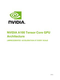
3 V and V power supplies Software and hardware controlled power-down 100-lead TQFP_EP package Integrated 1024 word 32-bit RAM PLL REFCLK multiplier Parallel datapath interface Internal oscillator can be driven by a single crystal Phase modulation capability Amplitude modulation capability Multichip synchronization APPLICATIONS Agile local oscillator (LO) frequency synthesis Programmable clock generators FM chirp source for radar and scanning systems Test and measurement equipment Acousto-optic device drivers Polar modulators Fast frequency hopping FUNCTIONAL BLOCK DIAGRAM 14-BIT DAC1 GSPS DDS CORELINEARRAMPGENERATOR1024-ELEMENTRAMHI GH SPEED PARALLELDATA INTERFACETIMING AND CONTROLSERIAL CONTROLDATA PORTREFCLKMULTIPLIER06479-001AD9910 Figure 1.
4 AD9910 Data Sheet Rev. E | Page 2 of 64 TABLE OF CONTENTS Features .. 1 Applications .. 1 Functional Block Diagram .. 1 Revision History .. 3 General Description .. 4 Specifications .. 5 Electrical Specifications .. 5 Absolute Maximum Ratings .. 8 Equivalent Circuits .. 8 ESD Caution .. 8 Pin Configuration and Function Descriptions .. 9 Typical Performance Characteristics .. 12 Application Circuits .. 15 Theory of Operation .. 16 Single Tone Mode .. 16 RAM Modulation Mode .. 17 Digital Ramp Modulation Mode .. 18 Parallel Data Port Modulation Mode .. 19 Mode Priority .. 21 Functional Block Detail.
5 22 DDS Core .. 22 14-Bit DAC Output .. 22 Inverse Sinc Filter .. 23 Clock Input (REF_CLK/REF_CLK) .. 23 PLL Lock Indication .. 26 Output Shift Keying (OSK) .. 26 Digital Ramp Generator (DRG) .. 27 RAM Control .. 32 Additional Features .. 41 Profiles .. 41 I/O_UPDATE, SYNC_CLK, and System Clock 41 Automatic I/O Update .. 42 Power-Down Control .. 42 Synchronization of Multiple Devices .. 43 Power Supply Partitioning .. 46 V Supplies .. 46 V Supplies .. 46 Serial Programming .. 47 Control Interface Serial I/O .. 47 General Serial I/O Operation .. 47 Instruction Byte .. 47 Serial I/O Port Pin Descriptions.
6 47 Serial I/O Timing Diagrams .. 48 MSB/LSB Transfers .. 48 Register Map and Bit Descriptions .. 49 Register Bit Descriptions .. 54 Outline Dimensions .. 61 Ordering Guide .. 61 Data Sheet AD9910 Rev. E | Page 3 of 64 REVISION HISTORY 10/2016 Rev. D to Rev. E Change to Figure 33 .. 25 5/2012 Rev. C to Rev. D Changes to Table 1 .. 8 Changes to Table 3 .. 12 Changes to Figure 39 .. 31 Changes to Synchronization of Multiple Devices Section .. 45 Changes to Table 18 .. 55 Changes to Table 20 .. 58 Changes to Table 26 .. 60 8/2010 Rev. B to Rev. C Changes to XTAL_SEL Input Parameter in Table 1.
7 8 Changes to Table 2 .. 9 Changes to Transmit Enable (TxENABLE) Section .. 21 12/2008 Rev. A to Rev. B Changes to Figure 5 Changes to I/O_UPDATE Pulse Width Parameter and Minimum Profile Toggle Period Parameter in Table 1 .. 7 Added XTAL_SEL Input Parameter in Table 1 .. 8 Changes to Table 3 .. 11 Changes to Figure 20 .. 16 Changes to Figure 22 .. 17 Changes to Figure 23 .. 18 Changes to Figure 24 .. 19 Changes to Figure 25 .. 20 Changes to REF_CLK/REF_CLK Overview Section .. 24 Changes to Crystal Driven REF_CLK/REF_CLK Section .. 25 Changes to PLL Lock Indication Section and Output Shift Keying (OSK) Section.
8 27 Changes to DRG Slope Control Section and Normal Ramp Generation 30 Changes to Drover Pin Section .. 32 Changes to Figure 43 .. 35 Changes to Figure 45 and Internal Profile Control Continuous Waveform Timing Diagram Section .. 38 Changes to Figure 47 .. 40 Changes to Figure 48 .. 41 Deleted I/O_UPDATE Pin Section .. 41 Changes to Profiles Section .. 42 Added I/O_UPDATE, SYNC_CLK, and System Clock Relationships Section .. 42 Added Figure 49; Renumbered Sequentially .. 42 Changes to Synchronization of Multiple Devices Section .. 44 Changes to DVDD ( ) (Pin 17, Pin 23, Pin 30, Pin 47, Pin 57, and Pin 64) Section and AVDD ( ) (Pin 89 and Pin 92) 47 Changes to Control Interface Serial I/O Section.
9 48 Changes to Table 17 .. 50 Changes to Table 19 .. 57 Changes to Table 20 and Table 21 .. 58 2/2008 Rev. 0 to Rev. A Changes to Features .. 1 Changes to REFCLK Multiplier Specification in Table 1 .. 5 Changes to Minimum Setup Time to 6 Changes to I/O Update/Profile[2:0] Timing Characteristics .. 6 Changes to TxENABLE/Data Setup Time (to PDCLK) and TxENABLE/Data Hold Time (to PDCLK) .. 6 Changes to Miscellaneous Timing 6 Changes to Table 3 .. 10 Changes to Figure 9, Figure 10, Figure 11, Figure 12, Figure 13, and Figure 14 .. 12 Changes to Figure 30 and Table 7 .. 24 Changes to Automatic I/O Update Section.
10 41 Added Table 16, Renumbered Sequentially .. 41 Changes to Figure 49 to Figure 53 .. 43 Added Power Supply Partitioning Section .. 46 Changes to General Serial I/O Operation Section .. 47 Changes to Table 17 .. 49 Changes to Ta b l e 1 9 .. 56 Changes to Table 20 .. 57 Added Table 32 .. 60 5/2007 Revision 0: Initial Version AD9910 Data Sheet Rev. E | Page 4 of 64 GENERAL DESCRIPTION The AD9910 is a direct digital synthesizer (DDS) featuring an integrated 14-bit DAC and supporting sample rates up to 1 GSPS. The AD9910 employs an advanced, proprietary DDS technology that provides a significant reduction in power con-sumption without sacrificing performance.