Transcription of ADP1055-EVALZ User Guide - Analog Devices
1 ADP1055-EVALZ user Guide UG-710. One Technology Way Box 9106 Norwood, MA 02062-9106, Tel: Fax: Evaluating the 240 Watts adp1055 Digital Controller for Isolated Power Supply with PMBus Interface FEATURES ADDITIONAL EQUIPMENT NEEDED. Full support evaluation kit for the adp1055 The USB-I2C connector, ADP-I2C-USB-Z, with Driver CD. 240 W full bridge topology (adjustable to phase shifted full (must order separately from Analog Devices , Inc.). bridge topology). GENERAL DESCRIPTION. Rated power of 12 V dc, 20 A. PMBus Revision compliant with PEC and extended This evaluation board, together with a daughter card, allows manufacturer specific commands you to evaluate the adp1055 as a power supply application. 32-bit password protection with command masking With the USB to I2C connector, and the graphical user interface 64 address selections (16 base addresses, expandable to 64) (GUI), the adp1055 on the evaluation board can be interfaced 6 PWM control signals, 625 ps resolution with a PC via a USB port.
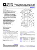
2 Duty cycle double update rate The evaluation board is set up to act as an isolated PSU with Fast line voltage feedforward a rated load of 12 V, 20 A from a 38 V dc to 60 V dc source. Redundant programmable OVP. Connectors on the evaluation board provide synchronization, Frequency synchronization as well as share bus and PMBus interfaces, allowing direct Soft-start and soft-stop functionality parallel evaluation when multiple evaluation boards are Droop current sharing connected in parallel to a common bus. On-board tests for housekeeping functions PMBus communication Multiple test points allow easy access to all critical points/pins. Software GUI. EVALUATION KIT CONTENTS. ADP1055-EVALZ evaluation board ADP1055DC1- evalz daughter card EVALUATION BOARD SETUP 12386-001.
3 Figure 1. adp1055 Evaluation Board PLEASE SEE THE LAST PAGE FOR AN IMPORTANT. WARNING AND LEGAL TERMS AND CONDITIONS. Rev. B | Page 1 of 43. UG-710 ADP1055-EVALZ user Guide TABLE OF CONTENTS. Features .. 1 Fault Response Window .. 14. Evaluation Kit Contents .. 1 VIN Window .. 15. Additional Equipment Needed .. 1 IIN Window .. 16. General Description .. 1 VOUT Window .. 16. Evaluation Board Setup .. 1 IOUT Window .. 17. Revision History .. 2 POUT Window .. 18. Evaluation Board Overview .. 3 Temperature Window .. 18. Power Board and Power Train Overview .. 3 PGOOD and GPIO Windows .. 19. adp1055 Daughter Card .. 3 32-Bit Keycode .. 19. Auxilary Power Board Circuit .. 3 Command Masking .. 19. 4 Active Clamp Snubber .. 20. Connectors .. 4 Digital Control 22.
4 Specifications .. 4 Efficiency Curves .. 25. Getting Started .. 5 Thermal Performance .. 25. Caution .. 5 GUI 55s Settings File .. 26. Hardware .. 5 Schematics and Artwork .. 31. Software GUI .. 6 ADP1055-EVALZ Schematic .. 31. Powering Up .. 7 ADP1055-EVALZ Layout .. 33. Evaluating the 9 ADP1055DC1- evalz Schematic .. 36. PWM and SR Window .. 9 ADP1055DC1- evalz Layout .. 37. CTRL and PSON Window .. 11 Bill of Materials .. 39. Soft-Start Window .. 12. Soft-Stop Window .. 13. REVISION HISTORY. 4/15 Rev. A to Rev. B. Changes to Figure 91 .. 31. Changes to Figure 92 .. 32. Changes to Table 5 .. 39. 2/15 Rev. 0 to Rev. A. Added Figure 47; Renumbered Sequentially .. 16. Changes to Figure 83 Caption and Figure 84 Caption .. 23. Changes to Figure 85 Caption and Figure 86 Caption.
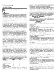
5 24. Change to Figure 92 .. 32. Change to Table 5 .. 39. 6/14 Revision 0: Initial Version Rev. B | Page 2 of 43. ADP1055-EVALZ user Guide UG-710. EVALUATION BOARD OVERVIEW. This ADP1055-EVALZ evaluation board and ADP1055DC1- The primary current is sensed using a current transformer T1. evalz daughter card feature the adp1055 in a dc-to-dc that provides primary fast and accurate over current protection switching power supply in full bridge topology with whereas the secondary side current (that is, the load current) is synchronous rectification operating at 125 kHz switching sensed using a sense resistor (R5, R9). frequency. adp1055 DAUGHTER CARD. Figure 4 shows the block diagram of the evaluation board. The The daughter card is shown in Figure 2. The adp1055 daughter circuit is designed to provide a rated load of 12 V, 20 A from a card consists of a V LDO that powers the adp1055 IC.
6 The dc input voltage source of 38 V dc to 60 V dc. The adp1055 PWMs for the primary switches (OUTA to OUTD) and for the provides functions, including output voltage regulation, secondary switches (SR1 and SR2) are connected from the synchronization, constant current control, pre-bias start up, daughter board to the power board and comprehensive protection functions. The evaluation kit consists of a power board, daughter card, and the auxiliary circuit board. POWER BOARD AND POWER TRAIN OVERVIEW. The power board is shown in Figure 1. Referring to the Schematics and Artwork section, the circuit components are 12386-002. described as follows. The primary and secondary H bridges are formed with MOSFETs QA through QD (primary side) and MOSFETs Q30, Q34, Q38, and Q40 (secondary side).
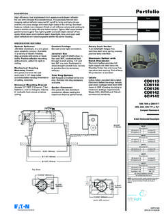
7 Figure 2. adp1055 Mounted on Daughter Card Transformer T2 provides the isolation. The output filter consists AUXILARY POWER BOARD CIRCUIT. of L8 and a capacitor bank (C48, C49, C51, C70, C73, and C74). This is the main power stage. The active snubber is made up of The auxiliary power board, included in the kit, is shown in clamp capacitor C192, MOSFET Q23 (pMOS), and driver U19. Figure 3. The auxiliary power circuit provides 9 V on the primary side and 9 V and 5 V (derived using a Zener diode). Additional circuitry around the power train is described as on the secondary side. The approximate minimum operating follows. The input filter consists of a single state LC (L10 and voltage of the auxiliary power board is 30 V. C6-13). Components U2 and U5 are half bridge 4 A drivers based on the Analog Devices , Inc.
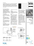
8 , iCoupler technology that provides gate drive for driving the primary H bridge. Secondary side H bridge drivers consist of U20 and U21. 12386-003. Figure 3. Auxiliary Power Board 38V TO 60V DC FULL BRIDGE SYNC 12V, 20A. RECTIFIER. MOSFET adp1055 I2C INTERFACE. DRIVERS DAUGHTER CARD SOCKET. SR1. AND. SR2 LDO OR 5V FROM USB. ADuM3223. iCoupler +DRIVER. OUTA. TO. OUTD. VDD_PRI = 9V 5V. AUXILLARY PSU. PRIMARY = +9V. 12386-004. SECONDARY1 = +9V VDD_SEC = 9V. SECONDARY2 = +5V. Figure 4. ADP1055-EVALZ Evaluation Board Block Diagram Rev. B | Page 3 of 43. UG-710 ADP1055-EVALZ user Guide APPLICATIONS Table 1. Evaluation Board Connections High efficiency, high power density, isolated dc-to-dc power Connector Function supplies include JP1 VIN+, dc Input Intermediate bus converters JP2 VIN , ground return for dc input J12 VOUT+, dc output Paralleled power supply systems J12 VOUT , return for dc output Server, storage, industrial, networking, and infrastructure J5 adp1055 daughter card connector J6, J7 I2C connector CONNECTORS J4 Auxiliary power board connector The connections to the ADP1055-EVALZ evaluation board are shown in Table 1.
9 Table 2 shows the details about these I2C/PMBus Connector on adp1055 Daughter Card connectors. Table 2. J6 Connections (Left to Right). Pin Function 1 5V. 2 SCL. 3 SDA. 4 AGND. SPECIFICATIONS. Table 3. Evaluation Board Connection Specifications Parameter Symbol Min Typ Max Unit Test Conditions/Comment Input Voltage VIN 38 48 60 V. Output Voltage VOUT 12 V. Output Current IOUT 20 A. Operation Temperature TA 25 50 C Natural convection 25 85 C Airflow = 200 LFM or above Efficiency 94 % VIN = 48 V, VOUT = 12 V, IOUT = 20 A. Switching Frequency fsw 125 kHz Output Voltage Ripple 200 mV VIN = 48 V, VOUT = 12 V, IOUT = 20 A. Dimension Excluding standoff Length in Width in Component Height in Rev. B | Page 4 of 43. ADP1055-EVALZ user Guide UG-710. GETTING STARTED.
10 CAUTION Precision digital multimeters (HP34401 or equivalent). This evaluation board uses high voltages and currents. Extreme USB to I2C connector ADP-I2C-USB-Z as shown in caution should be taken, especially on the primary side, to Figure 5. This must be ordered from Analog Devices . ensure your safety. It is strongly advised to switch off the Portable DMM (Fluke Corp.) for measuring up to 25 A dc evaluation board when not in use. A current limited, isolated current (optional). dc source is recommended at input. Evaluation Board Configurations HARDWARE The evaluation board is preconfigured with the default settings Evaluation Equipment to operate the power supply at the rated load. No additional DC power supply capable of 38 V dc to 60 V dc, 10 A. configuration is necessary other than to turn on the hardware PSON switch.