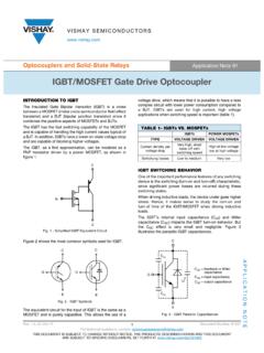
Transcription of AN3007 Using NEC Optocouplers as Gate Drivers …
1 A p p l i c at i o n N o t e AN 3007. Using NEC Optocouplers as gate Drivers in IGBT and Power MOSFET Applications by Van N. Tran Staff Applications Engineer, CEL Opto Semiconductors 1. Introduction todiode (PD), signal processing circuit, and large-current Rising concern for environmental issues and energy output circuit are also integrated into the device. savings is driving growth in the use of dynamic power control and inverters throughout the industrial, power, and home appliance markets. In the and Europe, NC 1 8 VCC. the use of general-purpose inverters and AC servos is UVLO. expanding rapidly, especially in the BRICs market. There LED. Output Voltage (V). ANODE 2 7 VO. has also been steady growth in the use of these devices Signal Output Processing drive in power-related fields like wind and solar generation, Circuit Circuit CATHODE 3 PD 6 VO.
2 Two markets that are expected to grow well into the future. Power semiconductors such as Insulated gate Bipolar Transistors (IGBT) and Power MOSFETs are be- NC 4. Shield 5 VEE. ing used in large quantities in the inverters employed in power-related equipment in all these fields. NEC's PS9552, PS9553, PS9301 and PS9401-2 are Figure 2-1 PS9552 Equivalent Circuit high-speed Optocouplers designed specifically for gate driving these IGBTs and Power MOSFETs. A newly developed BiCMOS process enables the light- receiving IC to provide a large output current (IO = Table 1-1 NEC gate Driver Optocouplers for IGBT/MOSFET max) with low operating circuit current (ICC = 2 mA typ). It also enables high- ABSOLUTE MAXIMUM RATINGS. temperature operation (Ta = 100 C. BV VCC IO(PEAK) ICCH/ICCL IFLH tPLH/tPHL PWD CMH/CML uF.)
3 Part No. Package max). Moreover, a transparent conduc- ( ) (V) (A) (mA) (mA) ( s) ( s) (kV/ s +5V min.) VCC = 15V. tive shield between the IRED and the +HV DC (P Lin PS9552 1 DIP8 5000 35 5/5 5 25/25. light receiving IC provides for superb PS9301 SDIP6 5000 35 3/3 5 15/15. noise resistance characteristics be- RG. PS9401-22 SSOP16 5000 35 3/3 5 15/15 tween input and output. Three PS9553 DIP8 5000 35 3/3 5 15/15 An Under-Voltage Lock Out (UVLO) Phase Output NOTES 1. Built-in UVLO function 2. Two channel version function protects both the PS9552 and VEE = 5 V. the IGBT when input signal drops or in In this application note, NEC's PS9552 Insulated gate other conditions where the IGBT could be damaged. HV DC (N Lin Driver optocoupler is used as an example to describe the characteristics, the internal gate drive circuits, the exter- PS9552 Features nal gate resistance requirements, and the details of gate Large output peak current (IO = max).)
4 Driver optocoupler power dissipation in relation to the High-speed switching (tPLH/ tPHL = s max). MOSFET/IGBT gate charge, based on the desired switch- ing frequency to turn on and off the MOSFET / IGBT. Large operating voltage range (VCC VEE = 15 30 V). VGS gate Source Voltage (V). Qg Built-in UVLO (Under-Voltage Lock Out) function 2. PS9552 Overview High instantaneous common mode rejection voltage VDR. Figure 2-1 shows the equivalent circuit of the PS9552, (CMH, CML = 15 kV/ s min.) Peak drive an 8-pin DIP digital, high-speed optocoupler that incor- Voltage porates a GaAlAs Infrared emitting diode (IRED) on the A PS9552 Truth Table is provided on the next page. More input side and a single-chip IC on the output side. A pho- details and a data sheet are available at Qgs Qgd Q gate Charge (nC).
5 AN 3007. 4. Designing an IGBT gate drive Circuit Using the PS9552. Table 2-1 PS9552 Truth Table 14. Electronic control of motors and AC circuits gives an intel- VCC VEE VCC VEE. IRED Voltage Rise Voltage Drop Output NCligent 1 power system a wide range of dynamic 8 VCCflexibility. 12. (Turn-On) (Turn-Off ) (VO) Computer algorithms UVLOcan take charge of systems and op- erateLED. them with a fine degree of control. 10. Output Voltage (V). OFF 0 to 30 V 0 to 30V L ANODE 2 7 VO. The basic circuit Signal shown Output in Figure 4-1 below outlines ON 0 to 11 V 0 to L 8. the fundamentalProcessing hardware Circuit connections, from the system drive Circuit ON 11 to to 12V Transition CATHODE control 3 PD on the left to the three-phase 6output input VO on the 6. ON to 30V 12 to 30V H right. The PS9552 as shown serves as the optical isola- NCtion 4 and driver for one of the power transistors, 5 VEE shown 4.
6 Shield V UVL. 3. UVLO Under-Voltage Lock Out Function ranked in pairs for each phase of the output. 2. One PS9552 Isolated gate Driver is required for When gate voltage to the IGBT drops, power dissipation each power transistor. The control system on the left is increases and the IGBT heats up, which can lead to 0. shown with a +5V supply. The output of the PS9552 is breakdown. When the VCC VEE power supply voltage to shown with +15V and 5V, which are electrically inde- Po the PS9552 is insufficient to protect the IGBT, the UVLO. pendent from the driving data input supply. The power function in the PS9552 maintains a low level Vo output transistors can have voltages of over +600V connected to protect both devices. to them from a separate supply. When the VCC VEE power supply voltage to the PS9552 is low (when the VCC VEE power supply uF.)
7 Voltage rises from 0 V), the VO output is main- +5V VCC = 15V. +HV DC (P Line). tained at a low level up to VUVLO+, even if the IRED. is on (Figure 3-1). Conversely, when the VCC VEE. drops (changes to a negative voltage), the VO out- RG. Three put is held at a high level until VUVLO , but when it Phase drops lower than VUVLO , the VO output is lowered Output to the low output level even if the IRED is on. VEE = 5 V. Based on this characteristic, if the VCC VEE. HV DC (N Line). power supply voltage of the PS9552 drops below VUVLO ( to 12 V) due to some anomaly in the IGBT drive circuit, the VO output of the PS9552 becomes Figure 4-1 Example of an IGBT drive circuit Using the PS9552. low level in approximately s even if the IRED is on. The gate resistance settings described in and are implemented.
8 Thereafter, if the VCC VEE power supply voltage exceeds VUVLO+ (11 to ), the VO output returns to high level This Isolated gate Driver solution enables a multi-sup- VGS gate Source Voltage (V). in approximately s (when IRED on). ply system to work, Qg providing data flow from the input to action at the output. Besides optical isolation between Figure 3-1 Output vs. Power Supply Voltage the power supply and power transistor, the PS9552 also VDR. provides the gate drive , eliminating Peak the need for any ad- 14 drive ditional drive 12 Calculation of Minimum Value of IGBT. external gate Resistance RG'. 10 Qgs Qgd Output Voltage (V). From the perspective of the optocoupler : 8 Q gate Charge (nC). The external gate resistance RG' must be selected so the UVLO HYS. peak output current IOL(PEAK) of the PS9552 does not ex- P.
9 6. ceed its maximum rating. The minimum value of RG' can 4 be approximated Using the following equation: 14. V UVLO ( V) V UVLO+ ( V) 1000nC. 2 12 RG' {(VCC VEE) VOL }/IOL(PEAK) (Equation ). 500nC. J 100nC. 10 VCC VEE the difference between the power supply volt- E SW ( J). 0 5 10 15 20 8 ages of the PS9552. (When negative voltage is not used, Power Supply Voltage V CC V EE (V) 6 VEE = 0V). 4 . 2. AN 3007. 14. 12. VOL equals the low-level output voltage of the PS9552. Where: 10. The minimum value of the external gate resistance Qgs = the gate - source charge Output Voltage (V). 8. RG' is calculated based on the following conditions: Qgd = the gate -drain charge IOL(PEAK) = UVLO. A HYS Qg = the total gate charge at which VGS equals the peak 6. drive voltage VDR or the charge that must be applied VCC VEE = 20 V.
10 4 to the gate , 14. either to swing it by a given amount or to VOL = 2 V Voltage V UVLO ( V). drop at IOL = A V UVLO+ ( V) achieve full switching. 2 NCcurves Refer to 1 8 VCC. in Figure 4-2 VOL vs. IOL Characteristics. 12. UVLO The equation for the gate charge is: From Equation : Q =10C x V. Output Voltage (V). 0 ANODE. 5 2 10 15 20 7 VO. Power Supply RG' Voltage {(VCC VVCCEE )V EESignal V(V). OL}/I OL(PEAK). Output Where Q is 8 the total charge Processing drive Circuit Circuit = (20. CATHODE 3 2) PD 6 VO The relationship UVLO HYS. between gate capacitance, switching 6. = W time, and the gate driver current is: 4. 5. NC 4. Shield 5 VEE dQ/dt = C x dV/dt = IG. V UVLO ( V) V UVLO+ ( V). 100 C Or the current 2 to be delivered to the gate is: 4 25 C. Line). 40 C IG = Qg / ts 0 5 10 15 20.