Transcription of AN88 - Ceramic Input Capacitors Can Cause Overvoltage ...
1 Application Note 88. March 2001. Ceramic Input Capacitors Can Cause Overvoltage Transients Goran Perica A recent trend in the design of portable devices has been Building the Test Circuit to use Ceramic Capacitors to filter DC/DC converter inputs. To illustrate the problem, a typical 24V wall adapter used Ceramic Capacitors are often chosen because of their in notebook computer applications was connected to the small size, low equivalent series resistance (ESR) and Input of a typical notebook computer DC/DC converter. The high RMS current capability. Also, recently, designers have DC/DC converter used was a synchronous buck converter been looking to Ceramic Capacitors due to shortages of that generates from a 24V Input .
2 Tantalum Capacitors . The block diagram of the test setup is shown in Figure 1. Unfortunately, using Ceramic Capacitors for Input filtering The inductor LOUT represents the lumped equivalent can Cause problems. Applying a voltage step to a Ceramic inductance of the lead inductance and the output EMI filter capacitor causes a large current surge that stores energy inductor found in some wall adapters. The output capaci- in the inductances of the power leads. A large voltage tor in the wall adapter is usually on the order of 1000 F;. spike is created when the stored energy is transferred for our purposes, we can assume that it has low ESR in from these inductances into the Ceramic capacitor.
3 These the 10m to 30m range. The equivalent circuit of the voltage spikes can easily be twice the amplitude of the wall adapter and DC/DC converter interface is actually Input voltage step. a series resonant tank, with the dominant components being LOUT, CIN and the lumped ESR (the lumped ESR. Plug In the Wall Adapter at Your Own Risk must include the ESR of CIN, the lead resistance and the The Input voltage transient problem is related to the power- resistance of LOUT). up sequence. If the wall adapter is plugged into an AC outlet The Input capacitor, CIN, must be a low ESR device, capable and powered up first, plugging the wall adapter output into of carrying the Input ripple current .
4 In a typical notebook a portable device can Cause Input voltage transients that computer application, this capacitor is in the range of 10 F. could damage the DC/DC converters inside the device. L, LT, LTC, LTM, Linear Technology and the Linear logo are registered trademarks of Linear Technology Corporation. All other trademarks are the property of their respective owners. WALL ADAPTER SW1 DC/DC CONVERTER. LOUT. 1 H to 10 H. M1. + COUT CIN. AC Input 1000 F 22 F M2 LOAD. 35V Ceramic . OUTPUT CABLE. 3 FEET TO 10 FEET AN88 F01. Figure 1. Block Diagram of Wall Adapter and Portable Device Connection an88f AN88-1.
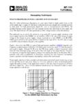
5 Application Note 88. to 100 F. The exact capacitor value depends on a number The waveform with 10 F and 10 H (trace R2) looks a of factors but the main requirement is that it must handle bit better. The peak is still around 50V. The flat part of the Input ripple current produced by the DC/DC converter. the waveform R2 following the peak indicates that the The Input ripple current is usually in the range of 1A to synchronous MOSFET M1, inside of the DC/DC converter 2A. Therefore, the required Capacitors would be either one in Figure 1, is avalanching and taking the energy hit. Traces 10 F to 22 F Ceramic capacitor, two to three 22 F tantalum R3 and R4 peak at around 41V and are for a 22 F capacitor Capacitors or one to two 22 F OS-CON Capacitors .
6 With 1 H and 10 H inductors, respectively. Turning On the Switch When switch SW1 in Figure 1 is turned on, the mayhem starts. Since the wall adapter is already plugged in, there is 24V across its low impedance output capacitor. On the other hand, the Input capacitor CIN is at 0V potential. What happens from t = 0s is pretty basic. The applied Input voltage will Cause current to flow through LOUT. CIN will begin charging and the voltage across CIN will ramp up toward the 24V Input voltage. Once the voltage across CIN has reached the output voltage of the wall adapter, the energy stored in LOUT will raise the voltage across CIN Figure 2.
7 Input Voltage Transients Across Ceramic Capacitors further above 24V. The voltage across CIN will eventually reach its peak and will then fall back to 24V. The voltage Table 1. Peak Voltages of Waveforms In Figure 2. across CIN may ring for some time around the 24V value. TRACE LIN ( H) CIN ( F) VIN PEAK (V). The actual waveform will depend on the circuit elements. CH1 1 10 R2 10 10 50. If you intend to run this circuit simulation, keep in mind that the real-life circuit elements are very seldom linear R3 1 22 41. under transient conditions. For example, the Capacitors may R4 10 22 41. undergo a change of capacitance (Y5V Ceramic Capacitors Input Voltage Transients with Different Input Elements will loose 80% of the initial capacitance under rated Input voltage).
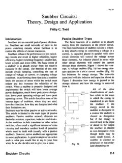
8 Also, the ESR of Input Capacitors will depend Different types of Input Capacitors will result in different on the rise time of the waveform. The inductance of EMI- transient voltage waveforms, as shown in Figure 3. The suppressing inductors may also drop during transients reference waveform for 22 F capacitor and 1 H inductor due to the saturation of the magnetic material. is shown in the top trace (R1); it peaks at The waveform R2 in Figure 3 shows what happens when Testing a Portable Application a transient voltage suppressor is added across the Input . Input voltage transients with typical values of CIN and The Input voltage transient is clamped but not eliminated.
9 LOUT used in notebook computer applications are shown It is very hard to set the voltage transient's breakdown in Figure 2. Figure 2 shows Input voltage transients for CIN voltage low enough to protect the DC/DC converter and values of 10 F and 22 F with LOUT values of 1 H and 10 H. far enough from the operating DC level of the Input source (24V). The transient voltage suppressor P6KE30A that The top waveform shows the worst-case transient, with a was used was too close to starting to conduct at 24V. 10 F capacitor and 1 H inductor. The voltage across CIN. Unfortunately, using a transient voltage suppressor with peaks at with a 24V DC Input .
10 The DC/DC converter a higher voltage rating would not provide a sufficiently may not survive repeated exposure to low clamping voltage. an88f AN88-2. Application Note 88. The waveforms R3 and R4 are with a 22 F, 35V AVX TPS To keep the Input filter design small, it is desirable to use type tantalum capacitor and a 22 F, 30V Sanyo OS-CON Ceramic Capacitors because of their high ripple current capacitor, respectively. With these two Capacitors , the tran- ratings and low ESR. To start the design, the minimum sients have been brought to manageable levels. However, value of the Input capacitor must first be determined.