Transcription of BSS138DW - Diodes Incorporated
1 BSS138DW Document number: DS30203 Rev. 13 - 2 1 of 6 January 2014 Diodes Incorporated BSS138DW DUAL N- channel enhancement MODE field EFFECT TRANSISTOR Product Summary V(BR)DSS RDS(ON) max ID max TA = +25 C 50V @ VGS = 10V 200mA Description This MOSFET has been designed to minimize the on-state resistance (RDS(on)) and yet maintain superior switching performance, making it ideal for high efficiency power management applications. Applications Load Switch Features Low On-Resistance Low Gate Threshold Voltage Low Input Capacitance Fast Switching Speed Totally Lead-Free & Fully RoHS Compliant (Notes 1 & 2) Halogen and Antimony Free.
2 Green Device (Notes 3) Qualified to AEC-Q101 Standards for High Reliability Mechanical Data Case: SOT-363 Case Material: Molded Plastic. Green Molding Compound. UL Flammability Classification Rating 94V-0 Moisture Sensitivity: Level 1 per J-STD-020 Terminals: Matte Tin Finish annealed over Alloy 42 leadframe. Solderable per MIL-STD-202, Method 208 Terminal Connections: See Diagram Weight: grams (approximate) Ordering Information (Note 4) Part Number Case Packaging BSS138DW -7-F SOT-363 3000/Tape & Reel Notes: 1. No purposely added lead. Fully EU Directive 2002/95/EC (RoHS) & 2011/65/EU (RoHS 2) compliant. 2.
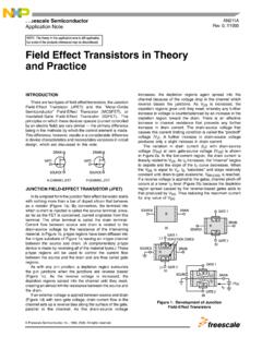
3 See for more information about Diodes Incorporated s definitions of Halogen- and Antimony-free, "Green" and Lead-free. 3. Halogen- and Antimony-free "Green products are defined as those which contain <900ppm bromine, <900ppm chlorine (<1500ppm total Br + Cl) and <1000ppm antimony compounds. 4. For packaging details, go to our website at Marking Information Date Code Key Year 2005 2006 2007 2008 2009 2010 2011 2012 2013 2014 2015 2016 2017 2018 2019 Code S T U V W X Y Z A B C D E F G Month Jan Feb Mar Apr May Jun Jul Aug Sep Oct Nov Dec Code 1 2 3 4 5 6 7 8 9 O N D SOT-363 TOP VIEW K38K38 YMYMS1D1D2S2G1G2 TOP VIEW Internal SchematicK38 = Product Type Marking Code YM = Date Code Marking for SAT (Shanghai Assembly/ Test site)
4 YM = Date Code Marking for CAT (Chengdu Assembly/ Test site) Y or Y = Year (ex: A = 2013) M = Month (ex: 9 = September) K38K38 YMYM BSS138DW Document number: DS30203 Rev. 13 - 2 2 of 6 January 2014 Diodes Incorporated BSS138DW Maximum Ratings (@TA = +25 C, unless otherwise specified.) Characteristic Symbol BSS138DW Units Drain-Source Voltage VDSS 50 V Drain-Gate Voltage (Note 7) VDGR 50 V Gate-Source Voltage Continuous VGSS 20 V Drain Current (Note 5) Continuous ID 200 mA Thermal Characteristics (@TA = +25 C, unless otherwise specified.) Characteristic Symbol BSS138DW Units Total Power Dissipation (Note 5) PD 200 mW Thermal Resistance, Junction to Ambient R JA 625 C/W Operating and Storage Temperature Range TJ, TSTG -55 to +150 C Electrical Characteristics (@TA = +25 C, unless otherwise specified.)
5 Characteristic Symbol Min Typ Max Unit Test Condition OFF CHARACTERISTICS (Note 6) Drain-Source Breakdown Voltage BVDSS 50 75 V VGS = 0V, ID = 250 A Zero Gate Voltage Drain Current IDSS A VDS = 50V, VGS = 0V Gate-Body Leakage IGSS 100nA VGS = 20V, VDS = 0V ON CHARACTERISTICS (Note 6) Gate Threshold Voltage VGS(th) V VDS = VGS, ID = 250 A Static Drain-Source On-Resistance RDS (ON) VGS = 10V, ID = Forward Transconductance gFS 100 mS VDS =25V, ID = , f = DYNAMIC CHARACTERISTICS Input Capacitance Ciss 50 pF VDS = 10V, VGS = 0V, f = Output Capacitance Coss 25 pF Reverse Transfer Capacitance Crss pF SWITCHING CHARACTERISTICS Turn-On Delay Time tD(ON) 20 ns VDD = 30V, ID = , RGEN = 50 Turn-Off Delay Time tD(OFF) 20 ns Notes: 5.
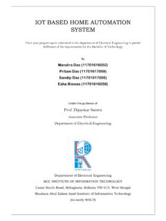
6 Device mounted on FR-4 PCB, 1 inch x inch x inch; pad layout as shown on Diodes Inc. suggested pad layout document AP02001, which can be found on our website at 6. Short duration pulse test used to minimize self-heating effect. 7. RGS 20K . BSS138DW Document number: DS30203 Rev. 13 - 2 3 of 6 January 2014 Diodes Incorporated BSS138DW , DRAIN-SOURCE CURRENT (A)DV , DRAIN-SOURCE VOLTAGE (V)Fig. 1 Drain-Source Current vs. Drain-Source VoltageDST = 25 Cj V = = = = = , GATE-SOURCE VOLTAGE (V)Fig. 2 Transfer , DRAIN-SOURCE CURRENT (A)D-55 C 150 C 25 C V = , JUNCTION TEMPERATURE ( C)Fig. 3 Drain-Source On Resistance vs.
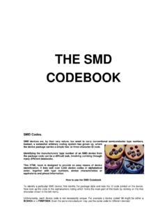
7 Junction = 10 VGSV = = = , NORMALIZED DRAIN-SOURCE ON-RESISTANCE ( )DS(ON) , GATE THRESHOLD VOLTAGE (V)GS(th)T , JUNCTION TEMPERATURE ( C)Fig. 4 Gate Threshold Voltage vs. Junction Temperaturej1252501500I , DRAIN-CURRENT (A)Fig. 5 Drain-Source On-Resistance vs. C -55 C 25 C V = , DRAIN-SOURCE ON-RESISTANCE ( )DS(ON) 0I , DRAIN-CURRENT (A)Fig. 6 Drain-Source On-Resistance vs. C -55 C 25 C V = , DRAIN-SOURCE ON-RESISTANCE ( )DS(ON) BSS138DW Document number: DS30203 Rev. 13 - 2 4 of 6 January 2014 Diodes Incorporated BSS138DW , DRAIN-CURRENT (A)Fig. 7 Drain-Source On-Resistance vs. Drain-CurrentD150 C -55 C 25 C V = , DRAIN-SOURCE ON-RESISTANCE ( )DS(ON) , DRAIN-CURRENT (A)Fig.
8 8 Drain-Source On-Resistance vs. Drain-CurrentD150 C -55 C 25 C V = 10 VGSR, DRAIN-SOURCE ON-RESISTANCE ( )DS(ON) I, DIODE CURRENT (A) , DIODE FORWARD VOLTAGE (V)Fig. 9 Body Diode Current vs. Body Diode C -55 C 25 C C, CAPACITANCE (pF)110100V , DRAIN-SOURCE VOLTAGE (V)Fig. 10 Capacitance vs. Drain-Source VoltageDS051015202530V = 0Vf = 1 MHzGSCrssCossCiss BSS138DW Document number: DS30203 Rev. 13 - 2 5 of 6 January 2014 Diodes Incorporated BSS138DW Package Outline Dimensions Please see AP02002 at for latest version. Suggested Pad Layout Please see AP02001 at for the latest version. SOT363 DimMinMax Typ A B C D Typ F H J 0 K L M 0 8 - All Dimensions in mm Dimensions Value (in mm) Z G X Y C1 C2 AMJLDBCHKFXZYC1C2C2G BSS138DW Document number: DS30203 Rev.
9 13 - 2 6 of 6 January 2014 Diodes Incorporated BSS138DW IMPORTANT NOTICE Diodes Incorporated MAKES NO WARRANTY OF ANY KIND, EXPRESS OR IMPLIED, WITH REGARDS TO THIS DOCUMENT, INCLUDING, BUT NOT LIMITED TO, THE IMPLIED WARRANTIES OF MERCHANTABILITY AND FITNESS FOR A PARTICULAR PURPOSE (AND THEIR EQUIVALENTS UNDER THE LAWS OF ANY JURISDICTION). Diodes Incorporated and its subsidiaries reserve the right to make modifications, enhancements, improvements, corrections or other changes without further notice to this document and any product described herein. Diodes Incorporated does not assume any liability arising out of the application or use of this document or any product described herein; neither does Diodes Incorporated convey any license under its patent or trademark rights, nor the rights of others.
10 Any Customer or user of this document or products described herein in such applications shall assume all risks of such use and will agree to hold Diodes Incorporated and all the companies whose products are represented on Diodes Incorporated website, harmless against all damages. Diodes Incorporated does not warrant or accept any liability whatsoever in respect of any products purchased through unauthorized sales channel . Should Customers purchase or use Diodes Incorporated products for any unintended or unauthorized application, Customers shall indemnify and hold Diodes Incorporated and its representatives harmless against all claims, damages, expenses, and attorney fees arising out of, directly or indirectly, any claim of personal injury or death associated with such unintended or unauthorized application.