Example: stock market
Dual 4-bit binary ripple counter
Dual 4-bit binary ripple counter 4. Functional diagram 001aad532 1CP 1 1 2 6 5 3 4 1MR 1Q0 1Q1 1Q2 1Q3 2CP 2 13 12 8 9 1 10 2MR 2Q0 2Q1 2Q2 2Q3 Fig. 1. Logic symbol 001aad533 CT = 0 CT 12 13 8 9 11 10 + 0 3 CT = 0 CT 2 1 6 5 3 4 + 0 3 CTR4 CTR4 Fig. 2. IEC logic symbol 001aad534 1CP 4-BIT BINARY RIPPLE COUNTER 4-BIT BINARY RIPPLE COUNTER 1 2 6 ...
Information
Domain:
Source:
Link to this page:
Documents from same domain
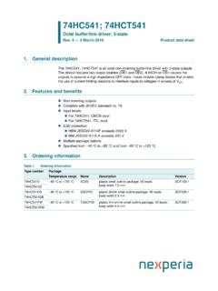
74HC541; 74HCT541 Octal buffer/line driver; 3-state
assets.nexperia.com1. General description The 74HC541; 74HCT541 is an octal non-inverting buffer/line driver with 3-state outputs. The device features two output enables (OE1 and OE2).

MMBT3904 NPN switching transistor - Nexperia
assets.nexperia.comDATA SHEET Product data sheet Supersedes data of 2002 Oct 04 2004 Feb 03 DISCRETE SEMICONDUCTORS MMBT3904 NPN switching transistor …

BZT52H series Single Zener diodes in a SOD123F …
assets.nexperia.com1. Product profile 1.1 General description General-purpose Zener diodes in a SOD123F small and flat lead Surface-Mounted Device (SMD) plastic package.
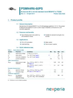
N-channel 60 V, 4.6 mΩ - Nexperia
assets.nexperia.com1. Product profile 1.1 General description Standard level N-channel MOSFET in a TO-220 package qualified to 175 °C. This product is designed and qualified for use in a wide range of industrial, communications and

PDTB113ZT PNP 500 mA, 50 V resistor-equipped transistor ...
assets.nexperia.com1. Product profile 1.1 General description 500 mA PNP Resistor-Equipped Transistor (RET) in a small SOT23 (TO-236AB) Surface-Mounted Device (SMD) plastic package.
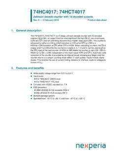
74HC4017; 74HCT4017 Johnson decade counter with 10 …
assets.nexperia.comThe 74HC4017; 74HCT4017 is a 5-stage Johnson decade counter with 10 decoded outputs (Q0 to Q9), an output from the most significant flip-flop (Q5-9), two clock inputs (CP0 and CP1) and an overriding asynchronous master reset input (MR).
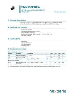
AEC-Q101 qualified • 1 kV ESD protected 3. Applications ...
assets.nexperia.comPMV130ENEA 40 V, N-channel Trench MOSFET 5 July 2018 Product data sheet 1. General description ... • 1 kV ESD protected • AEC-Q101 qualified 3. Applications • Relay driver • High-speed line driver ... Fig. 15.Gate charge waveform definitions aaa-011953 VSD (V) 0 0.4 0.8 1.2 2 1 3 4 IS (A) 0 Tj = 150 °C
PMDT290UCE 20 / 20 V, 800 / 550 mA N/P-channel Trench …
assets.nexperia.comPMDT290UCE All information provided in this document is subject to legal disclaimers. 2 J 0 8;*+ Product data sheet Rev. 1 — 6 October 2011 2 of 20
PMDT290UNE 20 V, 800 mA dual N-channel Trench MOSFET
assets.nexperia.com20 V, 800 mA dual N-channel Trench MOSFET Rev. 1 — 13 September 2011 Product data sheet Symbol Parameter Conditions Min Typ Max Unit ... (j-sp) thermal resistance from junction to solder point--115K/W Per device Rth(j-a) thermal resistance from junction to ambient in free air [1] - - 250 K/W.

PSSI2021SAY Constant current source in SOT353 package
assets.nexperia.comLED driver Figure 5 shows a typical application circuit for an LED driver. The constant current ensures a constant LED brightness. Switching the current ON/OFF The output can be switched ON and OFF by connecting a resistor-equipped transistor (RET, e.g. PDTC124XU) as shown in Figure 6.
Related documents
74HC573; 74HCT573 CC • For 74HC573: CMOS level
assets.nexperia.comThe 74HC573; 74HCT573 is an 8-bit D-type transparent latch with 3-state outputs. The device features latch enable (LE) and output enable (OE) inputs. When LE is HIGH, data at the inputs enter the latches. In this condition the latches are transparent, a latch output will change each time its corresponding D-input changes.

C S Chapter 7- Memory System Design DA 2/e
classes.engineering.wustl.eduFig. 7.4 An 8-bit register as a 1D RAM array The entire register is selected with one select line, and uses one R/W line Data bus is bi-directional, and buffered. (Why?) S 2/e C D A ... latch to drive the bit lines to the value stored in the latch. S 2/e C D A
Low-voltage translating 16-bit I2C-bus/SMBus I/O expander ...
www.nxp.comThe PCAL6416A is a 16-bit general-purpose I/O expander that provides remote I/O ... The input latch feature holds or latches the input pin state ... D P0_5 P1_2 P1_4 P1_5 E P0_6 VSS P1_0 P1_1 P1_3 P0_7 002aag244 INT Figure 5. Ball mapping for VFBGA24 (3 mm

VS1053b Datasheet - VLSI
www.vlsi.fito an 18-bit oversampling, multi-bit, sigma-delta DAC. The decoding is controlled via a serial control bus. In addition to the basic de- ... 1 Higher current can cause latch-up. 2 Must not exceed 3.6 V 4.2 Recommended Operating Conditions Parameter Symbol Min Typ Max Unit Ambient Operating Temperature -40 +85 C

A Brief Introduction to SystemVerilog
compas.cs.stonybrook.eduAccidental Latch Description •This is not combinational, because for certain values of b, f ... Five bit output can prevent overflow: 4’b1000 + 4’b1000 gives 5’b10000 logic signed [3:0] g, h, i; ... assign d = a*b; d = 4’0010 == 2 Underflow! Spring 2015 :: CSE 502 –Computer Architecture Sequential Logic

SN54/74LS192 SN54/74LS193 PRESETTABLE BCD/DECADE …
ece-classes.usc.eduPRESETTABLE 4-BIT BINARY UP/DOWN COUNTER The SN54/74LS192 is an UP/DOWN BCD Decade (8421) Counter and the SN54/74LS193 is an UP/DOWN MODULO-16 Binary Counter. Separate ... inputs, and latch each Q output in the LOW state. If one of the Clock inputs is LOW during and after a reset or load operation,

TXS0104E 4-Bit Bidirectional Voltage-Level Translator for ...
www.ti.com• Latch-Up Performance Exceeds 100 mA Per JESD 78, Class II • ESD Protection Exceeds JESD 22 – A Port • 2000-V Human-Body Model (A114-B) ... This 4-bit non-inverting translator uses two separate configurable power-supply rails. The A port is designed to track VCCA.

ECE 547 - UNIVERSITY OF MAINE 1 8-Bit Arithmetic Logic Unit
ece.umaine.eduD. 8 Bit ALU Circuit The 8-bit ALU was formed by combining three 4-bit ALU’s with 5 multiplexers as shown in Figure 2. The design of the 8-bit ALU is based on the use of a carry select line. The four lowest bits of the input are fed into one of the 4 bit ALU’s.