Transcription of FQP30N06L 60V LOGIC N-Channel MOSFET
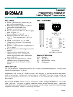
1 May 2001 QFETTMFQP30N06L 2001 Fairchild Semiconductor CorporationRev. A1. May 2001 FQP30N06L60V LOGIC N-Channel MOSFETG eneral DescriptionThese N-Channel enhancement mode power field effecttransistors are produced using Fairchild s proprietary,planar stripe, DMOS advanced technology has been especially tailored tominimize on-state resistance, provide superior switchingperformance, and withstand high energy pulse in theavalanche and commutation mode. These devices are wellsuited for low voltage applications such as automotive, DC/DC converters, and high efficiency switching for powermanagement in portable and battery operated 32A, 60V, RDS(on) = @VGS = 10 V Low gate charge ( typical 15 nC) Low Crss ( typical 50 pF)
2 Fast switching 100% avalanche tested Improved dv/dt capability 175 C maximum junction temperature ratingAbsolute Maximum Ratings TC = 25 C unless otherwise notedThermal Characteristics SymbolParameterFQP30N06 LUnitsVDSSD rain-Source Voltage60 VIDD rain Current - Continuous (TC = 25 C)32A- Continuous (TC = 100 C) Current - Pulsed(Note 1)128 AVGSSGate-Source Voltage 20 VEASS ingle Pulsed Avalanche Energy(Note 2)350mJIARA valanche Current(Note 1)32 AEARR epetitive Avalanche Energy(Note 1) Diode Recovery dv/dt(Note 3) Dissipation (TC = 25 C)79W- Derate above 25 CTJ, TSTGO perating and Storage Temperature Range-55 to +175 CTLM aximum lead temperature for soldering purposes,1/8" from case for 5 seconds300 CSymbolParameterTypMaxUnitsR JCThermal Resistance, C/WR CSThermal Resistance, C/WR JAThermal Resistance, C/W!
3 "!!!"""!"!!!"""SDG TO-220 FQP SeriesGSDFQP30N06 LRev. A1. May 2001 2001 Fairchild Semiconductor CorporationElectrical Characteristics TC = 25 C unless otherwise notedNotes:1. Repetitive Rating : Pulse width limited by maximum junction temperature2. L = 400 H, IAS = 32A, VDD = 25V, RG = 25 , Starting TJ = 25 C3. ISD 32A, di/dt 300A/us, VDD BVDSS, Starting TJ = 25 C 4. Pulse Test : Pulse width 300us, Duty cycle 2%5. Essentially independent of operating temperatureSymbolParameterTest ConditionsMinTypMaxUnitsOff CharacteristicsBVDSSD rain-Source Breakdown Voltage VGS = 0 V, ID = 250 A60----V BVDSS/ TJBreakdown Voltage Temperature Coefficient ID = 250 A, Referenced to 25 CIDSSZero Gate Voltage Drain CurrentVDS = 60 V, VGS = 0 V----1 AVDS = 48 V, TC = 150 C----10 AIGSSFGate-Body Leakage Current, ForwardVGS = 20 V, VDS = 0 V ----100nAIGSSRGate-Body Leakage Current, ReverseVGS = -20 V, VDS = 0 V -----100nAOn Characteristics VGS(th)Gate Threshold Voltage VDS = VGS, ID = 250 (on)
4 Static Drain-Source On-ResistanceVGS = 10 V, ID = 16 AVGS = 5 V, ID =16 A gFSForward TransconductanceVDS = 25 V, ID = 16 A --24--SDynamic CharacteristicsCissInput CapacitanceVDS = 25 V, VGS = 0 V, f = MHz --8001040pFCossOutput Capacitance--270350pFCrssReverse Transfer Capacitance--5065pFSwitching Characteristics td(on)Turn-On Delay TimeVDD = 30 V, ID = 16 A,RG = 25 --1540nstrTurn-On Rise Time--210430nstd(off)Turn-Off Delay Time--60130nstfTurn-Off Fall Time--110230nsQgTotal Gate ChargeVDS = 48 V, ID = 32 A,VGS = 5 V --1520nCQgsGate-Source Diode Characteristics and Maximum RatingsISMaximum Continuous Drain-Source Diode Forward Current----32 AISMM aximum Pulsed Drain-Source Diode Forward Current----128 AVSDD rain-Source Diode Forward VoltageVGS = 0 V, IS = 32 A Recovery TimeVGS = 0 V, IS = 32 A,dIF / dt = 100 A/ s --60--nsQrrReverse Recovery Charge--90--nC (Note 4) (Note 4, 5) (Note 4, 5)
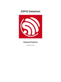
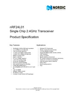
5 (Note 4) FQP30N06L 2001 Fairchild Semiconductor CorporationRev. A1. May 2001051015202530024681012 VDS = 30 VVDS = 48V Not e : ID = 32A VGS, Gate-Source Voltage [V]QG, Total Gate Charge [nC]10-11001010500100015002000 Ciss = Cgs + Cgd (Cds = shorted)Coss = Cds + CgdCrss = Cgd Notes : 1. VGS = 0 V 2. f = 1 MHzCrssCossCiss Capacitance [pF]VDS, Drain-Source Voltage [V] C Notes : 1. VGS = 0V 2. 250 s Pulse Test25 C IDR, Reverse Drain Current [A]VSD, Source-Drain voltage [V]0 20406080100120020406080 VGS = 10 VVGS = 5V Note : TJ = 25 C RDS(ON) [m ],Drain-Source On-ResistanceID, Drain Current [A]0246810100101102175 C25 C-55 C Notes : 1.
6 VDS = 25V 2. 250 s Pulse Test ID, Drain Current [A]VGS, Gate-Source Voltage [V]Typical CharacteristicsFigure 5. Capacitance CharacteristicsFigure 6. Gate Charge CharacteristicsFigure 3. On-Resistance Variation Current and Gate VoltageFigure 4. Body Diode Forward Voltage Variation vs. Source Current and TemperatureFigure 2. Transfer CharacteristicsFigure 1. On-Region Characteristics10-1100101100101102 VGSTop : V V V V V V VBottom : V Notes : 1.
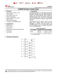
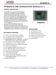
7 250 s Pulse Test 2. TC = 25 C ID, Drain Current [A]VDS, Drain-Source Voltage [V] FQP30N06L 2001 Fairchild Semiconductor CorporationRev. A1. May 200110-510-410-310-210-110010110-210-110 0 Notes : 1 . Z JC(t) = 0 C/W M a x . 2 . D u t y F a c t o r , D = t1/t2 3 . TJM - TC = PDM * Z JC(t)single pulseD= Z JC(t), Therm al R esponset1, S q u a re W a v e P u ls e D u ra tio n [s e c ]255075100125150175010203040 ID, Drain Current [A]TC, Case Temperature [ C]10-1100101102100101102 DC10 ms1 ms100 sOperation in This Area is Limited by R DS(on) Not es : 1. TC = 25 oC 2.
8 TJ = 175 oC 3. Single Pulse ID, Drain Current [A]VDS, Drain-Source Voltage [V] Notes : 1. VGS = 10 V 2. ID = 16 A RDS(ON), (Normalized)Drain-Source On-ResistanceTJ, Junction Temperature [oC] Notes : 1. VGS = 0 V 2. ID = 250 A BVDSS, (Normalized)Drain-Source Breakdown VoltageTJ, Junction Temperature [oC]Typical Characteristics (Continued)Figure 9. Maximum Safe Operating AreaFigure 10. Maximum Drain Currentvs. Case TemperatureFigure 7. Breakdown Voltage Variationvs. TemperatureFigure 8. On-Resistance Variationvs. TemperatureFigure 11. Transient Thermal Response Curvet1 PDMt2 FQP30N06L 2001 Fairchild Semiconductor CorporationRev.
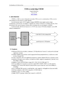
9 A1. May 2001 Gate Charge Test Circuit & Waveform Resistive Switching Test Circuit & Waveforms Unclamped Inductive Switching Test Circuit & WaveformsChargeVGS5 VQgQgsQgd3mAVGSDUTVDS300nF50K 200nF12 VSame Typeas DUTC hargeVGS5 VQgQgsQgd3mAVGSDUTVDS300nF50K 200nF12 VSame Typeas DUTVGSVDS10%90%td(on)trtontofftd(off)tfV DD5 VVDSRLDUTRGVGSVGSVDS10%90%td(on)trtontof ftd(off)tfVDD5 VVDSRLDUTRGVGSEAS =LIAS2----21--------------------BVDSS-VD DBVDSSVDDVDSBVDSSt pVDDIASVDS (t)ID (t)Time10 VDUTRGLIDt pEAS =LIAS2----21 EAS =LIAS2----21----21--------------------BV DSS-VDDBVDSSVDDVDSBVDSSt pVDDIASVDS (t)
10 ID (t)Time10 VDUTRGLLIDIDt pFQP30N06L 2001 Fairchild Semiconductor CorporationRev. A1. May 2001 Peak Diode Recovery dv/dt Test Circuit & WaveformsDUTVDS+_DriverRGSame Type as DUTVGS dv/dt controlled by RG ISDcontrolled by pulse period VDDLISD10 VVGS( Driver )ISD( DUT )VDS( DUT )VDDBody DiodeForward Voltage DropVSDIFM, Body Diode Forward CurrentBody Diode Reverse CurrentIRMBody Diode Recovery dv/dtdi/dtD =Gate Pulse WidthGate Pulse Period--------------------------DUTVDS+_ DriverRGSame Type as DUTVGS dv/dt controlled by RG ISDcontrolled by pulse period VDDLLISD10 VVGS( Driver )ISD( DUT )VDS( DUT )