Transcription of HMC194AMS8 / 194AMS8E - Analog Devices
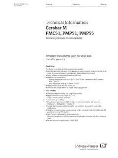
1 For price, delivery and to place orders: Hittite Microwave Corporation, 2 Elizabeth Drive, Chelmsford, MA 01824 Phone: 978-250-3343 Fax: 978-250-3373 Order On-line at Support: Phone: 978-250-3343 or - SPDt - SMt1 HMC194 AMS8 / MMIC SPDT SWITCHDC - 3 GHzGeneral DescriptionFeaturesFunctional DiagramUltra Small Package: MSOP8high isolation: 50 dBPositive control: 0/+3V to 0/+7 VElectrical Specifications, TA = +25 C, Vctl = 0/+5 Vdc, 50 Ohm SystemTypical Applicationsthe hMc194 AMS8 /hMc194 AMS8e is ideal for: Cellular/PCS Base Stations Portable Wireless MMDS & WirelessLANThe HMC194 AMS8 & HMC194 AMS8E are low-cost SPDT switches in 8-lead MSOP packages for use in applications which require high isolation between two RF paths. The Devices can control signals from DC to 3 GHz and have been optimized to provide extremely high isolation with minimal insertion loss in medium and low power applications.
2 On chip circuitry allows positive voltage control operation at very low DC cur-rents with control inputs compatible with CMOS and most TTL logic families. RF1 and RF2 are reflective opens when OFF . LossDc - Ghz Dc - Ghz Dc - Dc - Ghz Dc - Ghz Dc - Ghz Dc - Ghz5042312455453830dBdBdBdBReturn LossDc - Ghz Dc - Ghz2624dBdBInput Power for 1 dB Compression 0/+5V - Ghz2428dBmInput Third Order Intercept (Two-tone Input Power = +7 dBm Each Tone)0/+5V - Ghz4953dBmSwitching CharacteristicsDc - GhztRISE, tFALL (10/90% RF) tON , tOFF (50% CTL to 10/90% RF)320nsnsinformation furnished by Analog Devices is believed to be accurate and reliable. however, no responsibility is assumed by Analog Devices for its use, nor for any infringements of patents or other rights of third parties that may result from its use. Specifications subject to change without notice. No license is granted by implication or otherwise under any patent or patent rights of Analog Devices .
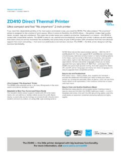
3 Trademarks and registered trademarks are the property of their respective price, delivery, and to place orders: Analog Devices , inc., One technology way, Box 9106, Norwood, MA 02062-9106 Phone: 781-329-4700 Order online at Application Support: Phone: 1-800- Analog -DFor price, delivery and to place orders: Hittite Microwave Corporation, 2 Elizabeth Drive, Chelmsford, MA 01824 Phone: 978-250-3343 Fax: 978-250-3373 Order On-line at Support: Phone: 978-250-3343 or - SPDt - SMt2 HMC194 AMS8 / MMIC SPDT SWITCHDC - 3 GHzInsertion LossIsolationReturn LossInput and dB Compression vs. Control VoltageInput Third OrderIntercept Point vs. Control VoltageTruth Table*Control Input Voltage Tolerances are Input*Control CurrentSignal Path StateA(Vdc)B(Vdc)ia(uA)Ib(uA)RF toRF1RF to RF20+ + +30+ + + +50+ +7-5+5 ONOFF+70+5-5 OFFON- 70- 60- 50- 40- 30- 20- 1000123RF1RF2 ISOLATION (dB)FREQUENCY (GHz)-3- LOSS (dB)FREQUENCY (GHz)- 40- 30- 20- 1000123S11S22 RETURN LOSS (dB)FREQUENCY (GHz)0102030405060357900 Mhz1900 Mhz3000 MhzTHIRD ORDER INTERCEPT (dBm)Control Input (Vdc) at 900 MhzP1dB at 900 at 1900 MhzP1dB at 1900 at 3000 MhzP1dB at 3000 MhzP & P1dB COMPRESSION (dBm)Control Input (Vdc)Information furnished by Analog Devices is believed to be accurate and reliable.
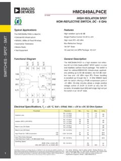
4 However, no responsibility is assumed by Analog Devices for its use, nor for any infringements of patents or other rights of third parties that may result from its use. Specifications subject to change without notice. No license is granted by implication or otherwise under any patent or patent rights of Analog Devices . Trademarks and registered trademarks are the property of their respective price, delivery, and to place orders: Analog Devices , Inc., One Technology Way, Box 9106, Norwood, MA 02062-9106 Phone: 781-329-4700 Order online at Application Support: Phone: 1-800- Analog -DFor price, delivery and to place orders: Hittite Microwave Corporation, 2 Elizabeth Drive, Chelmsford, MA 01824 Phone: 978-250-3343 Fax: 978-250-3373 Order On-line at Support: Phone: 978-250-3343 or - SPDt - SMt3 HMC194 AMS8 / MMIC SPDT SWITCHDC - 3 GHzAbsolute Maximum RatingsOutline DrawingRF Input Power (Vctl= 0V/+5V)+27 dBmControl Voltage Range (A & B) to + VdcHot Switch Power Level (Vctl= 0V/+5V)+24 dBmChannel Temperature150 cContinuous Pdiss (T= 85 C)(derate mW/ C above 85 C)300 mwthermal Resistance216 c/wStorage Temperature-65 to +150 cOperating Temperature-40 to +85 cESD Sensitivity (HBM)class 1 AELECTROSTATIC SENSITIVE DEVICEOBSERVE HANDLING PRECAUTIONSNote: DC blocking capacitors are required at ports RFC, RF1 and RF2.
5 Their value will determine the lowest transmission NumberPackage Body MaterialLead FinishMSL RatingPackage Marking [3]hMc194 AMS8 Low Stress Injection Molded PlasticSn/Pb SolderMSL1 [1]h194 AXXXXhMc194 AMS8eRoHS-compliant Low Stress Injection Molded Plastic 100% matte SnMSL1 [2]h194 AXXXX[1] Max peak reflow temperature of 235 C[2] Max peak reflow temperature of 260 C[3] 4-Digit lot number XXXXP ackage InformationNOTES:1. LEADFRAME MATERIAL: COPPER ALLOY2. DIMENSIONS ARE IN INCHES [MILLIMETERS].3. DIMENSION DOES NOT INCLUDE MOLDFLASH OF PER DIMENSION DOES NOT INCLUDE MOLDFLASH OF PER ALL GROUND LEADS MUST BE SOLDERED TO PCB RF CLASSIFIED AS MOISTURE SENSITIVITY LEVEL (MSL) furnished by Analog Devices is believed to be accurate and reliable. However, no responsibility is assumed by Analog Devices for its use, nor for any infringements of patents or other rights of third parties that may result from its use.
6 Specifications subject to change without notice. No license is granted by implication or otherwise under any patent or patent rights of Analog Devices . Trademarks and registered trademarks are the property of their respective price, delivery, and to place orders: Analog Devices , Inc., One Technology Way, Box 9106, Norwood, MA 02062-9106 Phone: 781-329-4700 Order online at Application Support: Phone: 1-800- Analog -DFor price, delivery and to place orders: Hittite Microwave Corporation, 2 Elizabeth Drive, Chelmsford, MA 01824 Phone: 978-250-3343 Fax: 978-250-3373 Order On-line at Support: Phone: 978-250-3343 or - SPDt - SMt4 HMC194 AMS8 / MMIC SPDT SWITCHDC - 3 GHzTypical Application CircuitNotes:1. Set logic gate and switch Vdd = +3V to +5V and use HCT series logic to provide a TTL driver Control inputs A/B can be driven directly with CMOS logic (HC) with Vdd of 3 to 7 Volts applied to the CMOS logic DC Blocking capacitors are required for each RF port as shown.
7 Capacitor value determines lowest frequency of Highest RF signal power capability is achieved with Control set to 0/+ Circuit BoardThe circuit board used in the final application should be generated with proper RF circuit design techniques. Signal lines at the RF port should have 50 Ohm impedance and the package ground leads should be connected directly to the ground plane similar to that shown above. The evalua-tion circuit board shown above is available from Hittite Microwave Corporation upon of Materials for Evaluation PCB 105143 [1]itemDescriptionJ1 - J3PC Mount SMA RF ConnectorJ4 - J6Dc Pinc1 - c3100 pF capacitor, 0402 , R2100 resistor, 0402 / 194 AMS8eSPDT SwitchPcB [2]107821 Evaluation PCB[1] Reference this number when ordering complete evaluation PCB[2] Circuit Board Material: Rogers 4350 Information furnished by Analog Devices is believed to be accurate and reliable.
8 However, no responsibility is assumed by Analog Devices for its use, nor for any infringements of patents or other rights of third parties that may result from its use. Specifications subject to change without notice. No license is granted by implication or otherwise under any patent or patent rights of Analog Devices . Trademarks and registered trademarks are the property of their respective price, delivery, and to place orders: Analog Devices , Inc., One Technology Way, Box 9106, Norwood, MA 02062-9106 Phone: 781-329-4700 Order online at Application Support: Phone: 1-800- Analog -D