Transcription of Human Body Model (HBM) vs. IEC 61000 4 2
1 Semiconductor Components Industries, LLC, 2010 September, 2010 Rev. 01 Publication Order Number:TND410/DTND410/DRev. 0, SEPT 2010 Human body Model (HBM)vs. IEC 61000 4 2 2 Overview Many ESD standards such as the Human body Model (HBM), Machine Model (MM), Charged Device Model (CDM), and IEC 61000 -4-2 have been developed to test for robustness and ensure ESD protection. Unfortunately, these standards are often misunderstood and sometimes used interchangeably, which can result in tested, protected systems that later fail in the consumer s hands. To ensure better product reliability, it is critical that today s design engineer understand the significant differences between manufacturing environment and system end user environment ESD testing. While most designers are familiar with the classic device level manufacturing tests that are applied to integrated circuits, the most common misunderstanding occurs between the HBM and IEC 61000 -4-2 standards.
2 These two very different standards are designed for very different purposes. Only the more stringent IEC 61000 -4-2 standard allows one to identify and correct ESD vulnerability of electronic products under real-world ESD stress conditions. The purpose of this paper is to describe the intended purpose and basic differences of the HBM and IEC61000-4-2 standards and testing methodologies. The Changing ESD Landscape: Increasing ESD Events, Decreasing On-Chip Protection Three important changes have contributed to the increased ESD vulnerability of today s electronic devices: Smaller Manufacturing Geometries - as manufacturing geometries for today's most advanced ICs decrease to 90 nm and less, the voltage and current levels that can cause ESD related failures for these devices also decrease. ESD damage can occur due to excessive voltage, high current levels, or a combination of both. High voltages can cause gate oxide punch-through, while excessive I2R levels can cause junction failures and metallization traces to melt.
3 As manufacturing geometries decrease, the voltage and current levels that can cause these failures also decrease. This has made it difficult to provide even relatively low levels of on-chip ESD protection. A Reduction in On-Chip Protection - increased susceptibility to ESD damage has been widely publicized as the Industry Council on ESD Target Specifications recently announced a move to reduce the standard level of on-chip ESD protection, making external ESD protection circuits even more critical for adequate system reliability. The focus of the Industry Council s efforts is to reduce the level of on-chip ESD protection, primarily aimed at providing adequate levels of ESD protection for manufacturing environments. They are not suggesting reducing system level ESD protection, which they suggest must remain at existing levels. The Changing Application Environment the proliferation of laptops, cell phones, MP3 players, digital cameras, and other hand-held mobile devices, used in uncontrolled environments ( , no wrist-grounding straps or conductive and grounded table surfaces).
4 In these environments, people touch I/O connector pins while connecting and disconnecting cables. Devices are subjected to constant ESD stress as users plug cameras, games, and other devices into their USB and video ports. A portable device can also build up a charge during normal usage and discharge that energy when connected to another device, such as a computer or a TV. The simple act of walking across a synthetic carpet and touching an exposed port on the outside of a digital TV can result in an ESD discharge greater than 35 kV. ESD discharges can occur directly at the port, or they can be discharged through a cable. This scenario is particularly dangerous to electronics equipment because the entire charge bypasses the connector s ground shield (if it has one) and is discharged directly into the system s electrical circuits. 3 Table 1: Static Voltage Generation Examples (Source: ESD Association) Examples of Static Voltage Generation At Different Levels of Relative Humidity (RH) Means of Generation 10-25% RH 65-90% RH Walking across carpet 35,000 V 1,500 V Walking across vinyl tile 12,000 V 250 V Worker at bench 6,000 V 100 V Poly bag picked up from bench 20,000 V 1,200 V Chair with urethane foam 18,000 V 1,500 V ESD Standards in the Manufacturing Environment ICs are inherently susceptible to ESD damage.
5 This damage can occur during the process of assembling the ICs into boards and finished systems, packaging, or in the field. There are several current methods for rating ICs for ESD in the manufacturing environment. The most common include: HBM - this standard is intended to simulate a person becoming charged and discharging from a bare finger to ground through the circuit under test. MM - intended to simulate a charged manufacturing machine, discharging through the device to ground. CDM - simulates an integrated circuit becoming charged and discharging to a grounded metal surface. The purpose of traditional ESD testing of integrated circuits in the manufacturing environment is very different than system level testing. HBM, MM and CDM tests are intended to ensure that integrated circuits survive the manufacturing process. Generally, manufacturers design in only enough protection for their device to survive being assembled into a finished system.
6 Processes such as packaging, final testing, shipment to a board assembly facility, placement on the circuit board, and the soldering process are performed in controlled ESD environments that limits the level of ESD stress to which the device is exposed. In the manufacturing environment, ICs are only specified to survive 2 kV HBM, although some have been specified as high as 8 kV, while others - particularly newer parts in very small geometry processes - can be 500 V or less. While HBM is usually sufficient for the controlled ESD environment of the factory floor, it is completely inadequate for system level testing. The levels of ESD strikes, both the voltages and the currents, can be much greater in the end user environment. For this reason, the industry uses a different testing standard for system level ESD testing. This standard is known as the IEC 61000 -4-2. IEC 61000 -4-2: The ESD Standard for System Level Testing The IEC standard is a system level test that replicates a charged person discharging to a system in a system end user environment.
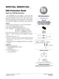
7 The purpose of the system level test is to ensure that finished products can survive normal operation and it is generally assumed that the user of the product will not take any ESD precautions to lower ESD stress to the product. The IEC 61000 -4-2 standard defines four standard levels of ESD protection, using two different testing methodologies. Contact discharge involves discharging an ESD pulse directly from the ESD test gun that is touching the device under test. This is the preferred method of testing. However, the standard provides for an alternate test methodology known as air discharge for cases where contact discharge testing is not possible. In the air discharge test, the ESD test gun is brought close to the device under test until a discharge occurs. The standards are defined so that each level is considered equivalent a Level 4 contact discharge of 8 kV is considered equivalent to a 15 kV air discharge. 4 Table 2.
8 IEC 61000 -4-2 Test Levels Contact Discharge Air Discharge Level Test Voltage kV Level Test Voltage kV 1 2 1 2 2 4 2 4 3 6 3 8 4 8 4 15 X Note 1 Special X Note 1 Special Notes 1. x is an open level.
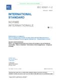
9 The level has to be specified in the dedicated equipment specification. If higher voltages than those are specified, special test equipment may be required. HBM versus IEC 61000 -4-2 There are several differences between the HBM and IEC 61000 -4-2 standard that are immediately obvious. The most important differences are as follows: the amount of current and I2R power released during a voltage strike the rise time of the voltage strike the number of voltage strikes repeated in the tests The Amount of Current and I2R Power Released During a Voltage Strike A key difference between these two standards is the peak current level associated with a strike. As shown in Table 3, the peak current discharged during an 8 kV HBM strike is less than the peak current discharged during a 2 kV IEC 61000 -4-2 strike and, at 8 kV (a common system level ESD requirement), the peak current for an IEC 61000 -4-2 strike is over 22 times higher than what most high performance semiconductors are designed to withstand.
10 Table 3. Peak current of HBM vs. IEC 61000 -4-2 ESD Standards Applied Voltage (kV) Peak Current (A) Human body Model Peak Current (A) IEC 61000 -4-2 2 4 6 8 10 5 The difference in current is critical to whether the ASIC will survive the ESD strike. Because high current levels can cause junction failures and metallization traces to melt, it is possible that a chip protected to 8 kV HBM can be destroyed by a 2 kV IEC 61000 -4-2 strike.