Transcription of LF353 Wide-Bandwidth JFET-Input Dual Operational …
1 + IN OUTIN +ProductFolderSample &BuyTechnicalDocumentsTools &SoftwareSupport &CommunityAn IMPORTANTNOTICEat the end of this datasheetaddressesavailability,warranty, changes,use in safety-criticalapplications,intellectual propertymattersand MARCH1987 REVISEDMARCH2016LF353 Wide-BandwidthJFET-InputDual OperationalAmplifier11 Features1 Low InputBiasCurrent50 pA Typical Low Hz Typical Low mA Typical HighInputImpedance1012 Typical Internally-TrimmedOffsetVoltage GainBandwidth3 MHzTypical HighSlewRate13 V/ s Typical2 Applications MotorIntegratedSystems:UPS Drivesand ControlSolutions:AC Inverterand VFDrives Renewables.
2 SolarInverters Pro AudioMixers Oscilloscopes3 DescriptionThisLF353deviceis a low-cost,high-speed, jfet -inputoperationa lamplifierwithverylow requireslow supplycurrentyet maintainsalargegain-bandwidthproductand a fast ,thematchedhigh-voltageJFET inputprovidesvery low inputbias and LF353can be usedin applicationssuchas high-speedintegrators,digital-to-analogc onverters,sample-and-holdcircuits,and LF353is characterizedfor operationfrom0 C to70 (1)PARTNUMBERPACKAGEBODYSIZE(NOM) LF353 DSOIC(8) (8) (1) For all availablepackages,see the orderableaddendumatthe end of the MARCH1987 : LF353 SubmitDocumentationFeedbackCopyright 1987 2016,TexasInstrumentsIncorporatedTableof Contents1 Pin Configurationand Applicationand Deviceand Mechanical,Packaging,and RevisionHistoryNOTE.
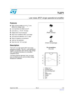
3 Pagenumbersfor previousrevisionsmay differfrompagenumbersin the (August1994)to RevisionCPage AddedESDR atingstable,FeatureDescriptionsection,De viceFunctionalModes,ApplicationandImplem entationsection,PowerSupplyRecommendatio nssection,Layoutsection,DeviceandDocumen tationSupportsection,andMechanical,Packa ging, 1IN+VCC VCC+2 OUT2IN 2IN+ MARCH1987 REVISEDMARCH2016 ProductFolderLinks: LF353 SubmitDocumentationFeedbackCopyright 1987 2016,TexasInstrumentsIncorporated5 Pin Configurationand FunctionsD or P Package8-PinSOICor PDIPTop ViewPin +3 INoninvertinginputVCC-4 Negativesupplyvoltage2IN+5 INoninvertinginput2IN-6 IInvertinginput2 OUT7 OOutputVCC+8 Positivesupplyvoltage4LF353 SLOS012C MARCH1987.
4 LF353 SubmitDocumentationFeedbackCopyright 1987 2016,TexasInstrumentsIncorporated(1)Stre ssesbeyondthoselistedunderAbsoluteMaximu mRatingsmay causepermanentdamageto the stressratingsonly,whichdo not implyfunctionaloperationof the deviceat theseor any otherconditionsbeyondthoseindicatedunder RecommendedOperatingConditions. Exposureto absolute-maximum-ratedconditionsfor extendedperiodsmay affectdevicereliability.(2)Unlessotherwi sespecified,the absolutemaximumnegativeinputvoltageis equalto the (unlessotherwisenoted)(1)MINMAXUNITVCC+S upplyvoltage18 VVCC Supplyvoltage 18 VVIDD ifferentialinputvoltage 30 VVII nputvoltage(2) 15 VDurationof outputshortcircuitUnlimitedsContinuousto tal mm (1/16inch)fromcasefor 10 s260 CTJJ unctiontemperature150 CTstgStoragetemperature 65150 C(1)JEDEC documentJEP155statesthat 500-VHBM allowssafe manufacturingwith a standardESDcontrolprocess.
5 (2)JEDEC documentJEP157statesthat 250-VCDM allowssafe manufacturingwith a (ESD)ElectrostaticdischargeHuman-bodymod el(HBM),per ANSI/ESDA/JEDECJS-001(1) 2000 VCharged-devicemodel(CDM),per JEDEC specificationJESD22-C101(2) (unlessotherwisenoted)MINMAXUNITVCC+ Supplyvoltage 18 VVCMC ommon-modevoltageVCC + 4 VCC+ 4 VTAO peratingtemperature070 C(1)For moreinformationabouttraditionaland new thermalmetrics,see theSemiconductorandICPackageThermalMetri csapplicationreport, (1) LF353 UNITD (SOIC)P (PDIP)8 PINS8 PINSR C/WR JC(top)Junction-to-case(top) C/WR C/W C/W MARCH1987 REVISEDMARCH2016 ProductFolderLinks: LF353 SubmitDocumentationFeedbackCopyright 1987 2016,TexasInstrumentsIncorporated(1)Full rangeis 0 C to 70 C(2)Inputbias currentsof a FET-inputoperationalamplifierare normaljunctionreversecurrents,whichare usedthat will maintainthe junctiontemperaturesas closeto the ambienttemperatureas possible.
6 (3)Supply-voltagerejectionratiois measuredfor bothsupplymagnitudesincreasingor 0 C to 70 C, VCC = 15 V (unlessotherwisenoted)PARAMETERTESTCONDI TIONSMINTYPMAXUNITVIOI nputoffsetvoltageVIC= 0, RS= 10 k TA= 25 C510mVFull range(1)13 VIOA veragetemperaturecoefficientof inputsoffsetvoltageVIC= 0, RS= 10 k 10 V/ CIIOI nputoffsetcurrent(2)VIC= 0TA= 25 C25100pATA= 70 C4nAIIBI nputbias current(2)VIC= 0TA= 25 C50200pATA= 70 C8nAVICRC ommon-modeinputvoltagerangeLowerlimit of range 11 12 VUpperlimit of range1115 VOMM aximumpeakoutputvoltageswingRL= 10 k 12 10 V, RL= 2 k TA= 25 C25100V/mVFull range(1)15riInputresistanceTJ= 25 C1012 CMRRC ommon-moderejectionratioRS 10 k 70100dBkSVRS upply-voltagerejectionratioSee(3) = 15 V, TA= 25 C, overoperatingfree-airtemperaturerange(un lessotherwisenoted)
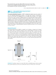
7 PARAMETERTESTCONDITIONSMINTYPMAXUNITVO1/ VO2 Crosstalkattenuationf = 1 kHz120dBSRS lewrate813V/ sB1 Unity-gainbandwidth3 MHzVnEquivalentinputnoisevoltagef = 1 kHz,RS= 20 18nV/ HzInEquivalentinputnoisecurrentf = 1 Hz6LF353 SLOS012C MARCH1987 : LF353 SubmitDocumentationFeedbackCopyright 1987 2016, MaximumPeakOutputVoltagevs FrequencyFigure2. MaximumPeakOutputVoltagevs LoadResistanceFigure3. Large-SignalDifferentialVoltageAmplifica tionand PhaseShiftvs FrequencyVICL= 100 pFRL= 2 k + MARCH1987 REVISEDMARCH2016 ProductFolderLinks: LF353 SubmitDocumentationFeedbackCopyright 1987 2016,TexasInstrumentsIncorporated7 ParameterMeasurementInformationFigure4.
8 Unity-GainAmplifier8LF353 SLOS012C MARCH1987 : LF353 SubmitDocumentationFeedbackCopyright 1987 2016,TexasInstrumentsIncorporated8 LF353deviceis a jfet -inputoperationalamplifierwith low inputbias and offsetcurrentsand fast (for highinputimpedance)coupledwith bipolaroutputstagesintegratedona outputis protectedagainstshortsdue to the resistive200- slewrate is the rate at whichan operationalamplifiercan changeits outputwhenthereis a changeon 13-V/ s poweredon whenthe supplyis be operatedas a single-supplyoperationalamplifieror dual-supplyamplifierdependingon the = = --VVOUTA =VINVsup++ MARCH1987 REVISEDMARCH2016 ProductFolderLinks.
9 LF353 SubmitDocumentationFeedbackCopyright 1987 2016,TexasInstrumentsIncorporated9 Applicationand ImplementationNOTEI nformationin the followingapplicationssectionsis not partof the TI componentspecification,and TI doesnot warrantits accuracyor s customersareresponsiblefor determiningsuitabilityof componentsfor test theirdesignimplementationto two independentamplifiersthat haveverylow inputbiascurrentwhichallowusinghigherres istanceresistorsin the upperinputcommonmoderangegoesto the lowercommonmoderangedoesnot includethe negativesupplyrail. Outputresistanceis 200 ohmstoprotectthe typicalapplicationfor an operationalamplifieris an amplifiertakesa positivevoltageonthe input ,and makesit a the samemanner,it also supplyvoltagemustbe chosensuchthat it is largerthanthe inputvoltagerangeand ,this applicationscalesa signalof V to V.
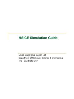
10 Settingthe supplyat 12 V is sufficienttoaccommodatethis gain requiredby the invertingamplifierusingEquation1 and Equation2.(1)(2)Oncethe desiredgain is determined,choosea valuefor RI or RF. Choosinga valuein the k rangeis desirablebecausethe amplifiercircuitusescurrentsin the mA part doesdrawtoo this example,choose10 k for RI and 36 k for RF, as shownin Equation3.(3) (ms)VINVOUT10LF353 SLOS012C MARCH1987 : LF353 SubmitDocumentationFeedbackCopyright 1987 2016,TexasInstrumentsIncorporatedTypical Application(continued) Inputand OutputVoltagesof the InvertingAmplifier10 PowerSupplyRecommendationsCAUTIONS upplyvoltageslargerthan36 V for a single-supplyor outsidethe rangeof 18 V for adual-supplycan permanentlydamagethe device(seetheAbsoluteMaximumRatings).