Transcription of LM741 Operational Amplifier - MIT
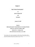
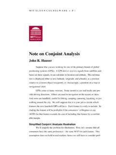
1 LM741 Operational AmplifierGeneral DescriptionThe LM741 series are general purpose Operational amplifi-ers which feature improved performance over industry stan-dards like the LM709. They are direct, plug-in replacementsfor the 709C, LM201, MC1439 and 748 in most amplifiers offer many features which make their applica-tion nearly foolproof: overload protection on the input andoutput, no latch-up when the common mode range is ex-ceeded, as well as freedom from LM741C is identical to the LM741 /LM741A except thatthe LM741C has their performance guaranteed over a 0 C to+70 C temperature range, instead of 55 C to +125 DiagramsTypical ApplicationMetal Can PackageDS009341-2 Note 1:LM741H is available per JM38510/10101 Order Number LM741H, LM741H/883(Note 1),LM741AH/883 or LM741 CHSee NS Package Number H08 CDual-In-Line or PackageDS009341-3 Order Number LM741J, LM741J/883, LM741 CNSee NS Package Number J08A, M08A or N08 ECeramic FlatpakDS009341-6 Order Number LM741W/883 See NS Package Number W10 AOffset Nulling CircuitDS009341-7 August 2000LM741 Operational Amplifier 2000 National Semiconductor Maximum Ratings(Note 2)If Military/Aerospace specified devices are required, please contact the National Semiconductor Sales Office/Distributors for availability and specifications.
2 (Note 7) LM741 ALM741LM741 CSupply Voltage 22V 22V 18 VPower Dissipation (Note 3)500 mW500 mW500 mWDifferential input Voltage 30V 30V 30 VInput Voltage (Note 4) 15V 15V 15 VOutput Short Circuit DurationContinuousContinuousContinuousOp erating Temperature Range 55 C to +125 C 55 C to +125 C0 C to +70 CStorage Temperature Range 65 C to +150 C 65 C to +150 C 65 C to +150 CJunction Temperature150 C150 C100 CSoldering InformationN-Package (10 seconds)260 C260 C260 CJ- or H-Package (10 seconds)300 C300 C300 CM-PackageVapor Phase (60 seconds)215 C215 C215 CInfrared (15 seconds)215 C215 C215 CSee AN-450 Surface Mounting Methods and Their Effect on Product Reliability for other methods of solderingsurface mount Tolerance (Note 8)400V400V400 VElectrical Characteristics(Note 5)ParameterConditionsLM741 ALM741LM741 CUnitsMinTypMaxMinTypMaxMinTypMaxInput Offset VoltageTA= 25 CRS 10 k 50 TA TAMAXRS 50 10 k input Offset15 V/ CVoltage DriftInput Offset VoltageTA= 25 C, VS= 20V 10 15 15mVAdjustment RangeInput Offset CurrentTA= 25 TA TAMAX7085500300nAAverage input CCurrent DriftInput Bias CurrentTA= 25 C30808050080500nATAMIN TA AInput ResistanceTA= 25 C, VS= TAMIN TA TAMAX, VS= 20 VInput Voltage RangeTA= 25 C 12 13 VTAMIN TA TAMAX 12 Characteristics(Note 5) (Continued)
3 ParameterConditionsLM741 ALM741LM741 CUnitsMinTypMaxMinTypMaxMinTypMaxLarge Signal Voltage GainTA= 25 C, RL 2k VS= 20V, VO= 15V50V/mVVS= 15V, VO= 10V5020020200V/mVTAMIN TA TAMAX,RL 2k ,VS= 20V, VO= 15V32V/mVVS= 15V, VO= 10V2515V/mVVS= 5V, VO= 2V10V/mVOutput Voltage SwingVS= 20 VRL 10 k 16 VRL 2k 15 VVS= 15 VRL 10 k 12 14 12 14 VRL 2k 10 13 10 13 VOutput Short CircuitTA= 25 C1025352525mACurrentTAMIN TA TAMAX1040mACommon-ModeTAMIN TA TAMAXR ejection RatioRS 10 k ,VCM= 12V70907090dBRS 50 ,VCM= 12V8095dBSupply Voltage RejectionTAMIN TA TAMAX,RatioVS= 20V to VS= 5 VRS 50 8696dBRS 10 k 77967796dBTransient ResponseTA= 25 C, Unity GainRise (Note 6)TA= 25 RateTA= 25 C, Unity sSupply CurrentTA= 25 ConsumptionTA= 25 CVS= 20V80150mWVS= 15V50855085mWLM741 AVS= 20 VTA=TAMIN165mWTA=TAMAX135mWLM741VS= 15 VTA=TAMIN60100mWTA=TAMAX4575mWNote 2: Absolute Maximum Ratings indicate limits beyond which damage to the device may occur.
4 Operating Ratings indicate conditions for which the device isfunctional, but do not guarantee specific performance Characteristics(Note 5) (Continued)Note 3:For operation at elevated temperatures, these devices must be derated based on thermal resistance, and Tjmax. (listed under Absolute Maximum Rat-ings ). Tj=TA+( jAPD).Thermal ResistanceCerdip (J)DIP (N)HO8 (H)SO-8 (M) jA(Junction to Ambient)100 C/W100 C/W170 C/W195 C/W jC(Junction to Case)N/AN/A25 C/WN/ANote 4:For supply voltages less than 15V, the absolute maximum input voltage is equal to the supply 5:Unless otherwise specified, these specifications apply for VS= 15V, 55 C TA +125 C ( LM741 /LM741A). For the LM741C/LM741E, these specifica-tions are limited to 0 C TA +70 6:Calculated value from: BW (MHz) = Time( s).
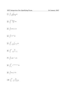
5 Note 7:For military specifications see RETS741X for LM741 and RETS741AX for 8:Human body model, k in series with 100 Dimensionsinches (millimeters) unless otherwise notedMetal Can Package (H)Order Number LM741H, LM741H/883, LM741AH/883, LM741AH-MIL or LM741 CHNS Package Number H08 CCeramic Dual-In-Line Package (J)Order Number LM741J/883NS Package Number Dimensionsinches (millimeters) unless otherwise noted (Continued)Dual-In-Line Package (N)Order Number LM741 CNNS Package Number N08E10-Lead Ceramic Flatpak (W)Order Number LM741W/883, LM741WG-MPR or LM741WG/883NS Package Number SUPPORT POLICYNATIONAL S PRODUCTS ARE NOT AUTHORIZED FOR USE AS CRITICAL COMPONENTS IN LIFE SUPPORTDEVICES OR SYSTEMS WITHOUT THE EXPRESS WRITTEN APPROVAL OF THE PRESIDENT AND GENERALCOUNSEL OF NATIONAL SEMICONDUCTOR CORPORATION.
6 As used herein:1. Life support devices or systems are devices orsystems which, (a) are intended for surgical implantinto the body, or (b) support or sustain life, andwhose failure to perform when properly used inaccordance with instructions for use provided in thelabeling, can be reasonably expected to result in asignificant injury to the A critical component is any component of a lifesupport device or system whose failure to performcan be reasonably expected to cause the failure ofthe life support device or system, or to affect itssafety or SemiconductorCorporationAmericasTel: 1-800-272-9959 Fax: 1-800-737-7018 Email: SemiconductorEuropeFax: +49 (0) 180-530 85 86 Email: Tel.
7 +49 (0) 69 9508 6208 English Tel: +44 (0) 870 24 0 2171 Fran ais Tel: +33 (0) 1 41 91 8790 National SemiconductorAsia Pacific CustomerResponse GroupTel: 65-2544466 Fax: 65-2504466 Email: SemiconductorJapan : 81-3-5639-7560 Fax: Operational AmplifierNational does not assume any responsibility for use of any circuitry described, no circuit patent licenses are implied and National reserves the right at any time without notice to change said circuitry and specifications.