Transcription of Low Distortion Mixer AD831 - Analog Devices
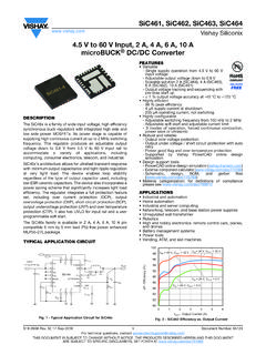
1 AD831 Low Distortion MixerFUNCTIONAL BLOCK DIAGRAM FEATURESD oubly Balanced MixerLow Distortion +24 dBm Third Order Intercept (IP3) +10 dBm 1 dB Compression PointLow LO Drive Required: 10 dBmBandwidth 500 MHz RF and LO Input Bandwidths 250 MHz Differential Current IF Output DC to >200 MHz Single-Ended Voltage IF OutputSingle- or Dual-Supply OperationDC Coupled Using Dual supplies All Ports May Be DC Coupled No Lower Frequency Limit Operation to DCUser- programmable power ConsumptionAPPLICATIONSHigh Performance RF/IF Mixer Direct to Baseband ConversionImage-Reject MixersI/Q Modulators and DemodulatorsPRODUCT DESCRIPTIONThe AD831 is a low Distortion , wide dynamic range, monolithic Mixer for use in such applications as RF to IF downconversion in HF and VHF receivers, the second Mixer in DMR base sta-tions, direct-to-baseband conversion.
2 Quadrature modulation and demodulation, and doppler shift detection in ultrasound imaging applications. The Mixer includes an LO driver and a low noise output amplifier and provides both user- programmable power consumption and third order intercept AD831 provides a +24 dBm third order intercept point for 10 dBm LO power , thus improving system performance andreducing system cost compared to passive mixers, by eliminating the need for a high power LO driver and its attendant shielding and isolation RF, IF, and LO ports may be dc or ac coupled when the Mixer is operating from 5 V supplies or ac coupled when oper-ating from a single-supply of 9 V minimum. The Mixer operates with RF and LO inputs as high as 500 MHz.
3 The Mixer s IF output is available as either a differential current output or a single-ended voltage output. The differential output is from a pair of open collectors and may be ac coupled via a trans-former or capacitor to provide a 250 MHz output bandwidth. In downconversion applications, a single capacitor connected across these outputs implements a low-pass filter to reduce harmonics directly at the Mixer core, simplifying output filtering. When building a quadrature-amplitude modulator or image reject Mixer , the differential current outputs of two AD831s may be summed by connecting them integral low noise amplifier provides a single-ended voltage output and can drive such low impedance loads as filters, 50 amplifier inputs, and A/D converters.
4 Its small signal bandwidth exceeds 200 MHz. A single resistor connected between pins OUT and FB sets its gain. The amplifier s low dc offset allows its use in such direct-coupled applications as direct-to-baseband conversion and quadrature-amplitude demodulation. The Mixer s SSB noise figure is dB at 70 MHz using its output amplifier and optimum source impedance. Unlike passive mixers, the AD831 has no insertion loss and does not require an external diplexer or passive programmable -bias feature allows the user to reduce power consumption, with a reduction in the 1 dB compression point and third-order intercept. This permits a tradeoff between dynamic range and power consumption.
5 For example, the AD831 may be used as a second Mixer in cellular and two-way radio base stations at reduced power while still providing a substantial performance improvement over passive HIGHLIGHTS1. 10 dBm LO Drive for a +24 dBm Output Referred Third Order Intercept Point2. Single-Ended Voltage Output3. High Port-to-Port Isolation4. No Insertion Loss5. Single- or Dual-Supply Operation6. dB Noise FigureRev. D Document Feedback Information furnished by Analog Devices is believed to be accurate and reliable. However, no responsibility is assumed by Analog Devices for its use, nor for any infringements of patents or other rights of third parties that may result from its use.
6 Specifications subject to change without notice. No license is granted by implication or otherwise under any patent or patent rights of Analog Devices . Trademarks and registered trademarks are the property of their respective owners. One Technology Way, Box 9106, Norwood, MA 02062-9106, Tel: 2018 Analog Devices , Inc. All rights reserved. Technical Support 2 AD831 SPECIFICATIONSAD831 3 ParameterConditions Min Typ Max Unit RF INPUT Bandwidth 10 dBm Signal Level, IP3 +20 dBm400 MHz IF and High Side InjectionSee Figure 1 1 dB Compression Point10dBm Common-Mode Range 1 V Bias CurrentDC Coupled160 500 A DC Input ResistanceDifferential or Common Capacitance2 pFIF OUTPUT Bandwidth Single-Ended Voltage Output, 3 dBLevel = 0 dBm, RL = 100 200 MHz Conversion Gain Terminals OUT and VFB Connected0dB Output Offset VoltageDC Measurement.
7 LO Input Switched 1 40 +15 +40 mV Slew Rate300 V/ s Output Voltage SwingRL = 100 , Unity Gain Short Circuit Current 75 mALO INPUT Bandwidth 10 dBm Input Signal Level400 MHz IF and High Side Injection Maximum Input Level 1+1 V Common-Mode Range 1+1 V Minimum Switching LevelDifferential Input Signal200 mV p-p Bias CurrentDC Coupled17 50 A ResistanceDifferential or Common Mode500 Capacitance2 pFISOLATION BETWEEN PORTS LO-to-RFLO = 100 MHz, RS = 50 , MHz IF70 dB LO-to-IFLO = 100 MHz, RS = 50 , MHz IF30 dB RF-to-IF RF = 100 MHz, RS = 50 , MHz IF45 dBDISTORTION AND NOISELO = 10 dBm, f = 100 MHz, IF = MHz Third Order InterceptOutput Referred, 100 mV LO Input24dBm Second Order InterceptOutput Referred, 100 mV LO Input62dBm 1 dB Compression PointRL = 100 , RBIAS = 10 dBm Noise Figure, SSBM atched Input, RF = 70 MHz, IF = Input, RF = 150 MHz, IF = MHz14dBPOWER supplies Recommended Supply Range Dual Supply VSingle Supply 911V Quiescent Current*For Best Third Order Intercept Point Performance100 125 mABIAS Pin Open Circuited*Quiescent current is subject to change without notice.
8 (TA = +25 C and VS = 5 V unless otherwise noted;all values in dBm assume 50 load.)REV. CREV. D 2 AD831 SPECIFICATIONSAD831 3 PIN DESCRIPTIONPin No. MnemonicDescription 1 VPPositive Supply Input 2 IFNM ixer Current Output 3 ANAmplifier Negative Input 4 GNDG round 5 VNNegative Supply Input 6 RFPRF Input 7 RFNRF Input 8 VNNegative Supply Input 9 VPPositive Supply Input10 LONL ocal Oscillator Input11 LOPL ocal Oscillator Input12 VPPositive Supply Input13 GNDG round14 BIASBias Input15 VNNegative Supply Input16 OUTA mplifier Output17 VFBA mplifier Feedback Input18 COMA mplifier Output Common19 APAmplifier Positive Input20 IFPM ixer Current OutputABSOLUTE MAXIMUM RATINGS1 Supply Voltage VS.
9 VInput Voltages RFHI, RFLO .. 3 VLOHI, LOLO .. 1 VInternal power Dissipation2 ..1200 mWOperating Temperature RangeAD831A .. 40 C to +85 CStorage Temperature Range .. 65 C to +150 CLead Temperature Range (Soldering 60 sec) ..300 CPIN CONFIGURATION20-Lead PLCC CAUTIONESD (electrostatic discharge) sensitive device. Electrostatic charges as high as 4000 V readily accumulate on the human body and test equipment and can discharge without detection. Although the AD831 features proprietary ESD protection circuitry, permanent damage may occur on Devices subjected to high energy electrostatic discharges.
10 Therefore, proper ESD precautions are recommended to avoid performance degradation or loss of Stresses above those listed under Absolute Maximum Ratings may cause permanent damage to the device. This is a stress rating only and functional operation of the device at these or any other conditions above those indicated in the operational section of this specification is not implied. Exposure to absolute maximum rating conditions for extended periods may affect device Thermal Characteristics: 20-Lead PLCC Package: JA = 110 C/W; JC = 20 C/W. Note that the JA = 110 C/W value is for the package measured while suspended in still air; mounted on a PC board, the typical value is JA = 90 C/W due to the conduction provided by the AD831 s package being in contact with the board, which serves as a heat sink.