Transcription of Low Noise, 90 MHz Variable Gain Amplifier Data Sheet AD603
1 Low Noise, 90 MHz Variable Gain AmplifierData Sheet AD603 Rev. K Information furnished by analog devices is believed to be accurate and reliable. However, no responsibility is assumed by analog devices for its use, nor for any infringements of patents or other rights of third parties that may result from its use. Specifications subject to change without notice. No license is granted by implication or otherwise under any patent or patent rights of analog devices . Trademarks and registered trademarks are the property of their respective owners. One Technology Way, Box 9106, Norwood, MA 02062-9106, : Fax: 1993 2012 analog devices , Inc. All rights reserved. FEATURES Linear-in-dB gain control Pin-programmable gain ranges 11 dB to +31 dB with 90 MHz bandwidth 9 dB to 51 dB with 9 MHz bandwidth Any intermediate range, for example 1 dB to +41 dB with 30 MHz bandwidth Bandwidth independent of Variable gain nV/ Hz input noise spectral density dB typical gain accuracy APPLICATIONS RF/IF AGC amplifiers Video gain controls A/D range extensions Signal measurements GENERAL DESCRIPTION The AD603 is a low noise, voltage-controlled Amplifier for use in RF and IF AGC systems.
2 It provides accurate, pin-selectable gains of 11 dB to +31 dB with a bandwidth of 90 MHz or +9 dB to 51+ dB with a bandwidth of 9 MHz. Any intermediate gain range may be arranged using one external resistor. The input referred noise spectral density is only nV/ Hz, and power consumption is 125 mW at the recommended 5 V supplies. The decibel gain is linear in dB, accurately calibrated, and stable over temperature and supply. The gain is controlled at a high impedance (50 M ), low bias (200 nA) differential input; the scaling is 25 mV/dB, requiring a gain control voltage of only 1 V to span the central 40 dB of the gain range. An overrange and underrange of 1 dB is provided whatever the selected range. The gain control response time is less than 1 s for a 40 dB change. The differential gain control interface allows the use of either differential or single-ended positive or negative control voltages. Several of these amplifiers may be cascaded and their gain control gains offset to optimize the system SNR.
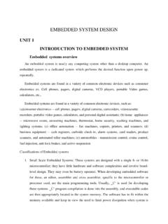
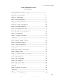
3 The AD603 can drive a load impedance as low as 100 with low distortion. For a 500 load in shunt with 5 pF, the total harmonic distortion for a 1 V sinusoidal output at 10 MHz is typically 60 dBc. The peak specified output is V minimum into a 500 load. The AD603 uses a patented proprietary circuit topology the X-AMP . The X-AMP comprises a Variable attenuator of 0 dB to dB followed by a fixed-gain Amplifier . Because of the attenuator, the Amplifier never has to cope with large inputs and can use negative feedback to define its (fixed) gain and dynamic performance. The attenuator has an input resistance of 100 , laser trimmed to 3%, and comprises a 7-stage R-2R ladder network, resulting in an attenuation between tap points of dB. A proprietary interpolation technique provides a continuous gain control function that is linear in dB. The AD603 is specified for operation from 40 C to +85 C. FUNCTIONAL BLOCK DIAGRAM SCALINGREFERENCEVGGAIN-CONTROLINTERFACEA D603 PRECISION PASSIVEINPUT ATTENUATORFIXED-GAINAMPLIFIER*NOMINAL LADDER NETWORKGPOSGNEGVINPCOMM0dB R R R R R2R2R2R2R2R2RR20 *694 * *VOUTFDBK00539-001 Figure 1.
4 AD603 Data Sheet Rev. K | Page 2 of 24 TABLE OF CONTENTS Features .. 1 Applications .. 1 General Description .. 1 Functional Block Diagram .. 1 Revision History .. 2 Specifications .. 3 Absolute Maximum Ratings .. 4 ESD Caution .. 4 Pin Configurations and Function Descriptions .. 5 Typical Performance Characteristics .. 6 Test Circuits .. 11 Theory of Operation .. 12 Noise Performance .. 12 The Gain Control Interface .. 13 Programming the Fixed-Gain Amplifier Using Pin Strapping .. 13 Using the AD603 in Cascade .. 15 Sequential Mode (Optimal SNR) .. 15 Parallel Mode (Simplest Gain Control Interface) .. 16 Low Gain Ripple Mode (Minimum Gain Error) .. 17 Applications Information .. 18 A Low Noise AGC Amplifier .. 18 Caution .. 19 Evaluation Board .. 20 Outline Dimensions .. 22 Ordering Guide .. 23 REVISION HISTORY 4/12 Rev. J to Rev. K Changes to Table 1 .. 3 Added Figure 10 and Figure 11; Renumbered Sequentially.
5 7 Added Test Circuits Section .. 11 Moved Figure 29 and Figure 30 .. 11 12/11 Rev. I to Rev. J Changes to Figure 1 .. 1 Changes to Evaluation Board Section .. 19 Changes to Figure 48 Through Figure 50 .. 19 Changes to Figure 51 Through Figure 54 .. 20 Added Figure 57 .. 22 5/07 Rev. G to Rev. H Changes to Layout .. 14 Changes to Layout .. 15 Changes to Layout .. 16 Inserted Evaluation Board Section, and Figure 48 to Figure 51 .. 19 Inserted Figure 52 and Table 4 .. 20 Changes to Ordering Guide .. 21 3/05 Rev. F to Rev. G Updated Format .. Universal Change to Features .. 1 Changes to General Description .. 1 Change to Figure 1 .. 1 Changes to Specifications .. 3 New Figure 4 and Renumbering Subsequent Figures .. 6 Change to Figure 10 .. 7 Change to Figure 23 .. 9 Change to Figure 29 .. 12 Updated Outline Dimensions .. 20 4/04 Rev. E to Rev. F Changes to Specifications .. 2 Changes to Ordering Guide .. 3 8/03 Rev.
6 D to Rev E Updated Format .. Universal Changes to Specifications .. 2 Changes to TPCs 2, 3, 4 .. 4 Changes to Sequential Mode (Optimal S/N Ratio) section .. 9 Change to Figure 8 .. 10 Updated Outline Dimensions .. 14 Data Sheet AD603 Rev. K | Page 3 of 24 SPECIFICATIONS @ TA = 25 C, VS = 5 V, 500 mV VG +500 mV, GNEG = 0 V, 10 dB to +30 dB gain range, RL = 500 , and CL = 5 pF, unless otherwise noted. Table 1. Parameter Conditions Min Typ Max Unit INPUT CHARACTERISTICS Input Resistance Pin 3 to Pin 4 97 100 103 Input Capacitance 2 pF Input Noise Spectral Density1 Input short-circuited nV/ Hz Noise Figure f = 10 MHz, gain = maximum, RS = 10 dB 1 dB Compression Point f = 10 MHz, gain = maximum, RS = 10 11 dBm Peak Input Voltage 2 V OUTPUT CHARACTERISTICS 3 dB Bandwidth VOUT = 100 mV rms 90 MHz Slew Rate RL 500 275 V/ s Peak Output2 RL 500 V Output Impedance f 10 MHz 2 Output Short-Circuit Current 50 mA Group Delay Change vs.
7 Gain f = 3 MHz; full gain range 2 ns Group Delay Change vs. Frequency VG = 0 V; f = 1 MHz to 10 MHz 2 ns Differential Gain % Differential Phase Degree Total Harmonic Distortion f = 10 MHz, VOUT = 1 V rms 60 dBc Third-Order Intercept f = 40 MHz, gain = maximum, RS = 50 15 dBm ACCURACY Gain Accuracy, f = 100 kHz; Gain (dB) = (40 VG + 10) dB 500 mV VG +500 mV 1 +1 dB TMIN to TMAX + dB Gain, f = MHz VG = V dB VG = V + + + dB VG = V + + + dB Output Offset Voltage3 VG = 0 V 20 mV TMIN to TMAX 30 mV Output Offset Variation vs. VG 500 mV VG +500 mV 20 mV TMIN to TMAX 30 mV GAIN CONTROL INTERFACE Gain Scaling Factor 100 kHz 40 dB/V TMIN to TMAX 38 42 dB/V MHz dB/V GNEG, GPOS Voltage Range4 + V Input Bias Current 50 100 250 nA Input Offset Current 10 nA Differential Input Resistance Pin 1 to Pin 2 50 M Response Rate Full 40 dB gain change 80 dB/ s POWER SUPPLY Specified Operating Range V Quiescent Current 17 mA TMIN to TMAX 20 mA 1 Typical open or short-circuited input; noise is lower when system is set to maximum gain and input is short-circuited.
8 This figure includes the effects of both voltage and current noise sources. 2 Using resistive loads of 500 or greater or with the addition of a 1 k pull-down resistor when driving lower loads. 3 The dc gain of the main Amplifier in the AD603 is ; therefore, an input offset of 100 V becomes a mV output offset. 4 GNEG and GPOS, gain control, and voltage range are guaranteed to be within the range of VS + V to +VS V over the full temperature range of 40 C to +85 C. AD603 Data Sheet Rev. K | Page 4 of 24 ABSOLUTE MAXIMUM RATINGS Table 2. Parameter Rating Supply Voltage VS V Internal Voltage VINP (Pin 3) 2 V Continuous VS for 10 ms GPOS, GNEG (Pin 1 and Pin2) VS Internal Power Dissipation 400 mW Operating Temperature Range AD603A 40 C to +85 C AD603S 55 C to +125 C Storage Temperature Range 65 C to +150 C Lead Temperature (Soldering, 60 sec) 300 C Stresses above those listed under Absolute Maximum Ratings may cause permanent damage to the device.
9 This is a stress rating only; functional operation of the device at these or any other conditions above those indicated in the operational section of this specification is not implied. Exposure to absolute maximum rating conditions for extended periods may affect device reliability. Table 3. Thermal Characteristics Package Type JA JC Unit 8-Lead SOIC 155 33 C/W 8-Lead CERDIP 140 15 C/W ESD CAUTION Data Sheet AD603 Rev. K | Page 5 of 24 PIN CONFIGURATIONS AND FUNCTION DESCRIPTIONS GPOS1 GNEG2 VINP3 COMM4 VPOS8 VOUT7 VNEG6 FDBK5AD603 TOP VIEW(Not to Scale)00539-002 Figure 2. 8-Lead SOIC Pin Configuration 00539-003 GPOS1 GNEG2 VINP3 COMM4 VPOS8 VOUT7 VNEG6 FDBK5AD603 TOP VIEW(Not to Scale) Figure 3. 8-Lead CERDIP Pin Configuration Table 4. Pin Function Descriptions Pin No. Mnemonic Description 1 GPOS Gain Control Input High (Positive Voltage Increases Gain). 2 GNEG Gain Control Input Low (Negative Voltage Increases Gain).
10 3 VINP Amplifier Input. 4 COMM Amplifier Ground. 5 FDBK Connection to Feedback Network. 6 VNEG Negative Supply Input. 7 VOUT Amplifier Output. 8 VPOS Positive Supply Input. AD603 Data Sheet Rev. K | Page 6 of 24 TYPICAL PERFORMANCE CHARACTERISTICS @ TA = 25 C, VS = 5 V, 500 mV VG +500 mV, GNEG = 0 V, 10 dB to +30 dB gain range, RL = 500 , and CL = 5 pF, unless otherwise noted. 00539-004VG (V) (dB)403020100 Figure 4. Gain vs. VG at 100 kHz and MHz 00539-005 GAIN VOLTAGE (V) ERROR (dB) Figure 5. Gain Error vs. Gain Control Voltage at 455 kHz, MHz, 45 MHz, 70 MHz 00539-006 PHASE (Degrees) 22522545901351800 45 90 135 180 FREQUENCY (Hz)100k1M10M100 MGAIN (dB)42301 2 1 4 5 3 6 GAINPHASE Figure 6. Frequency and Phase Response vs. Gain (Gain = 10 dB, PIN = 30 dBm) 00539-007 22522518013590450 45 90 180 135 PHASE (Degrees)FREQUENCY (Hz)100k1M10M100 MGAIN (dB)42130 1 2 3 4 5 6 GAINPHASE Figure 7.