Example: marketing
Charging and Discharging RC Circuits
Handout on RC Circuits. A.R. Neureuther Version Date 09/08/03 EECS 42 Intro. Digital Electronic, Fall 2003 Simplification for time behavior of RC Circuits Before any input change occurs we have a dc circuit problem (that is we can use dc circuit analysis to relate the output to the input). We call the time period during which the output
Tags:
Information
Domain:
Source:
Link to this page:
Documents from same domain
EE105 –Fall 2015 Microelectronic Devices and Circuits
inst.eecs.berkeley.eduSummary of MOS Single-Transistor Amplifiers MOS Common Source Common Source with Deg. Common Drain Common Gate Ri ∞ ∞ ∞ Small Ro Large Very Large Small Large

Diodes and Transistors
inst.eecs.berkeley.eduDiodes and Transistors 1. ... basic semiconductor physics. We won’t discuss the details because the point of this ... switch. Below the specified ...
HSPICE Tutorial - University of California, Berkeley
inst.eecs.berkeley.eduHSPICE Tutorial Contents 1 Introduction 1 ... ee105 spice tutorial example 1 - simple rc circuit in the Results Browser and double-clicking vs and vo to plot them in the graph. You may have been able to guess from the netlist, but you’ll see that vsis a …
Introduction to LabVIEW - University of California, …
inst.eecs.berkeley.eduIntroduction to LabVIEW 1. Introduction Welcome to the LabVIEW component of EE100! This lab is just a simple introduction to the graphical circuit simulation ...
Introduction to LabVIEW For Use in Embedded …
inst.eecs.berkeley.eduUC Berkeley EE249 Hugo.Andrade@ni.com Introduction to LabVIEW For Use in Embedded System Development
Introduction to Digital Systems - University of …
inst.eecs.berkeley.eduDepartment of EECS EE100/42-43 Spring 2007 Rev. 1 Introduction to Digital Systems 0. Acknowledgments Many thanks to Prof. Bernhard Boser and National Instruments for funding this project in the
EE126: Probability and Random Processes - Lecture 1 ...
inst.eecs.berkeley.eduprobability 4 The probabilities summed over all of the base outcomes always equals 1 Example: Toss a fair coin twice 1 Base outcomes are HH,HT,TH,TT 2 This covers all the possibilities. M.E. 3 Each of these outcomes is equally likely 4 Assign each outcome a probability of 0:25. The list (set) of base outcomes is called the Sample Space.
EECS 126 Probability and Random Processes: Course Syllabus ...
inst.eecs.berkeley.eduDescription: Probability is a mathematical discipline that allows one to reason about uncertainty: it helps us to predict uncertain events, to make better decisions under uncertainty, and to design and build systems. Throughout the course, we will teach you the fundamental ideas of probability and random processes along with the labs.

3-Phase Brushless DC Motor Pre-Driver
inst.eecs.berkeley.eduDescription The A4931 is a complete 3-phase brushless DC motor pre-driver . The device is capable of driving a wide range of N-channel power MOSFETs and can support motor supply voltages up to
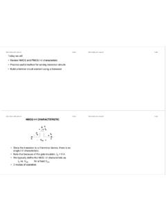
DS -V I G - EECS Instructional Support Group Home Page
inst.eecs.berkeley.eduG D S I D I G-V DS + + V G S _ NMOS I-V CHARACTERISTIC • Since the transistor is a 3-terminal device, there is no single I-V characteristic. • Note that because of the gate insulator, I G = 0 A. • We typically define the MOS I-V characteristic as I D vs. V DS for a fixed V GS. • 3 modes of operation
Related documents
Experiment Sequential Circuits 6 PART A: FLIP FLOPS
www.iium.edu.mySequential Circuits Experiment Objectives-To design a ripple counter using JK flip flop. -To connect a pre-settable counter and observe its operation. -To create different counter module by decoding outputs and loading preset inputs. Introduction A counter is a circuit consisting of a number of Flip Flop and gates
FLIP-FLOPS - California State University, Northridge
www.csun.edumemory 'and is, also the ' building, block for sequential:1qgic circuits. A . primary characteristic' af-sequential lOgiC: , circuj~ is . the ability to "remember" the state of ~e. inputs, i.e., memory. Flip-flops are formed from pairs of logic gates where the gate outputs are fed Into one ,of the inputs of the other gate in the pair. This
EMBEDDED SYSTEM DESIGN - Bharath Institute of Higher ...
www.bharathuniv.ac.inAt the top, we find VLSI circuits comprising of significant pieces of functionality: microprocessor, microcontrollers, FPGA‘s, CPLD, and ASIC. Our study of hardware side of embedded systems begins with a high level view of the ... It is an example of sequential digital logic, as it …
No Nonsense Technician Class - KB6NU's Ham Radio Blog
www.kb6nu.comexperimenting with antennas and electronic circuits. All kinds of people are amateur radio operators, also known as “hams.” Hams are young, old, men, women, boys and girls. Kids as young as seven years old have gotten amateur radio licenses, and many hams are active into their eighties and beyond. You never know who you'll run into on the ...

Seven-Segment Display - UMD
classweb.ece.umd.eduENEE 245: Digital Circuits & Systems Lab — Lab 8 Nexys2 seven-segment displays !e Nexys2 board uses the common anode method for its displays. !is means that all the anodes are tied together and connected through a pnp transistor to +3.3V, as shown in Figure 7.3. A
The Art of Assembly Language - Instituto de Computação
www.ic.unicamp.brThe Art of Assembly Language Page v 3.3.12.4 Hazards on the 8486 ..... 122
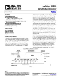
Low Noise, 90 MHz Variable Gain Amplifier Data Sheet AD603
www.analog.comLow Noise, 90 MHz Variable Gain Amplifier Data Sheet AD603 Rev. K Information furnished by Analog Devices is believed to be accurate and reliable. However, no