Transcription of NCP4304 - Secondary Side Synchronous Rectification Driver ...
1 NCP4304A, NCP4304B. Secondary side Synchronous Rectification Driver for High Efficiency SMPS Topologies The NCP4304A/B is a full featured controller and Driver tailored to control Synchronous Rectification circuitry in switch mode power supplies. Due to its versatility, it can be used in various topologies such 8. as flyback , forward and Half Bridge Resonant LLC. 1 1. The combination of externally adjustable minimum on and off times SOIC 8 DFN8. helps to fight the ringing induced by the PCB layout and other D SUFFIX MN SUFFIX. parasitic elements. Therefore, a reliable and noise less operation of the CASE 751 CASE 488AF. SR system is insured. The extremely low turn off delay time, high sink current capability MARKING DIAGRAMS. of the Driver and automatic package parasitic inductance 8. compensation system allow to maximize Synchronous Rectification 4304x NCP. MOSFET conduction time that enables further increase of SMPS ALYW G 4304x efficiency. G ALYWG. 1 G.
2 Finally, a wide operating VCC range combined with two versions of Driver voltage clamp eases implementation of the SR system in 24 V SOIC 8 DFN8. output applications. 4304x = Specific Device Code x = A or B. Features A = Assembly Location Self-Contained Control of Synchronous Rectifier in CCM, DCM, L = Wafer Lot Y = Year and QR flyback Applications W = Work Week Precise True Secondary Zero Current Detection with Adjustable G = Pb Free Package Threshold (*Note: Microdot may be in either location). Automatic Parasitic Inductance Compensation Input PINOUT INFORMATION. Typically 40 ns Turn off Delay from Current Sense Input to Driver Zero Current Detection Pin Capability up to 200 V VCC 1 8 DRV. Optional Ultrafast Trigger Interface for Further Improved MIN_TOFF 2 7 GND. MIN_TON 3 6 COMP. Performance in Applications that Work in Deep CCM TRIG/DIS 4 5 CS. Disable Input to Enter Standby or Low Consumption Mode Adjustable Minimum On Time Independent of VCC Level (NOTE: For DFN the exposed pad must be either unconnected or preferably connected to ground.)
3 Adjustable Minimum Off Time Independent of VCC Level The GND pin must be always connected to ground.). 5 A Peak Current Sink/Source Drive Capability Operating Voltage Range up to 30 V ORDERING INFORMATION. Gate Drive Clamp of Either 12 V (NCP4304A) or 6 V (NCP4304B) Device Package Shipping . Low Startup and Standby Current Consumption NCP4304 ADR2G SOIC 8 2,500 /. Maximum Frequency of Operation up to 500 kHz (Pb Free) Tape & Reel SOIC 8 Package NCP4304 BDR2G SOIC 8. (Pb Free). 2,500 /. Tape & Reel These are Pb Free Devices NCP4304 AMNTWG DFN8 4,000 /. (Pb Free) Tape & Reel Typical Applications Notebook Adapters NCP4304 BMNTWG DFN8 4,000 /. (Pb Free) Tape & Reel High Power Density AC/DC Power Supplies For information on tape and reel specifications, Gaming Consoles including part orientation and tape sizes, please All SMPS with High Efficiency Requirements refer to our Tape and Reel Packaging Specifications Brochure, BRD8011/D. Semiconductor Components Industries, LLC, 2016 1 Publication Order Number: March, 2016 Rev.
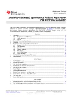
4 6 NCP4304 /D. NCP4304A, NCP4304B. NCP4304 . C2. RMIN_TOFF VCC DRV. MIN_TOFF GND. MIN_TON COMP. RMIN_TON TRIG/DIS CS. +Vbulk +Vout TR1. M1 M3. N2 +. C4. LLC. STAGE RTN. CONTROL. M2 N1. N3. C1 M4. NCP4304 . C3. RMIN_TOFF VCC DRV. MIN_TOFF GND. MIN_TON COMP. RMIN_TON TRIG/DIS CS. D1. OK1. Figure 1. Typical Application Example LLC Converter Vbulk + TR1. C1 R1 C2. +Vout D3. VCC M2 +. C5. + D4. C3 GND. flyback . CONTROL. CIRCUITRY C4. DRV M1 RMIN_TOFF. R3 VCC DRV. FB CS MIN_TOFF GND. MIN_TON COMP. R2 R4 TRIG/DIS CS. RMIN_TON. R5. D5. OK1. R6. Figure 2. Typical Application Example DCM or QR flyback Converter 2. NCP4304A, NCP4304B. PIN FUNCTION DESCRIPTION. Pin No. Pin Name Function Pin Description 1 VCC Supplies the Driver Supply terminal of the controller. Accepts up to 30 V continuously. 2 MIN_TOFF Minimum off time adjust Adjust the minimum off time period by connecting resistor to ground. 3 MIN_TON Minimum on time adjust Adjust the minimum on time period by connecting resistor to ground.
5 4 TRIG/DIS Forced reset input This ultrafast input turns off the SR MOSFET in CCM applications. Activates sleep mode if pulled up for more than 100 ms. 5 CS Current sense of the SR This pin detects if the current flows through the SR MOSFET and/or its body MOSFET diode. Basic turn off detection threshold is 0 mV. A resistor in series with this pin can modify the turn off threshold if needed. 6 COMP Compensation inductance Use as a Kelvin connection to auxiliary compensation inductance. If SR. connection MOSFET package parasitic inductance compensation is not used (like for SMT MOSFETs), connect this pin directly to GND pin. 7 GND IC ground Ground connection for the SR MOSFET Driver and VCC decoupling capacitor. Ground connection for minimum ton, toff adjust resistors and trigger input. GND pin should be wired directly to the SR MOSFET source terminal/soldering point using Kelvin connection. 8 DRV Gate Driver output Driver output for the SR MOSFET. VDD. toff_min Generator Start MINIMUM OFF.
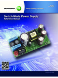
6 MIN_TOFF TIME. GENERATOR. Enable SET. Blanking of CS. VDD during toff_min, ton_min 100 mA. ZCD SET & &. DETECTION CS S Q DRV Out CS & Driver DRV. ZCD Reset R Q. COMPENSATION. & OR. VDD. Enable RESET. DRV Set Enable COMP. DRV Reset 1k5. VCC. MANAGEMENT VCC. UVLO. MINIMUM ON. MIN_TON TIME ton_min Generator Start GENERATOR. VDD TIMER Sleep Mode 100 ms INV. One shot GND. S Q. OR. ZCD Reset R Q. TRIG/DIS & INV. 10 mA VTH = 2 V. Trigger Blanking One shot INV. 120 ns 120 ns during DRV rising edge Figure 3. Internal Circuit Architecture 3. NCP4304A, NCP4304B. MAXIMUM RATINGS. Symbol Rating Value Unit VCC IC Supply Voltage to 30 V. VDRV Driver Output Voltage to 17 V. VCS Current Sense Input dc Voltage 4 to 200 V. VCsdyn Current Sense Input Dynamic Voltage (tpw = 200 ns) 10 to 200 V. VTRIG/DIS Trigger Input Voltage to 10 V. VMIN_TON, VMIN_TOFF MIN_TON and MIN_TOFF Input Voltage to 10 V. IMIN_TON, IMIN_TOFF MIN_TON and MIN_TOFF Current 10 to +10 mA. VCOMP Static Voltage Difference between COMP and GND Pins (Internally Clamped) 3 to 10 V.
7 VCOMP_dyn Dynamic Voltage Difference between COMP and GND Pins (tpw = 200 ns) 10 to 10 V. ICOMP Current into COMP Pin 5 to 5 mA. RqJA Thermal Resistance Junction-to-Air, SOIC A/B Versions 180 C/W. RqJA Thermal Resistance Junction-to-Air, DFN A/B Versions, 50 mm2 oz. Copper 180 C/W. Spreader RqJA Thermal Resistance Junction-to-Air, DFN A/B Versions, 600 mm2 oz. Copper 80 C/W. Spreader TJmax Maximum Junction Temperature 150 C. TSmax Storage Temperature Range 60 to +150 C. TLmax Lead Temperature (Soldering, 10 s) 300 C. ESD Capability, Human Body Model except Pin VCS Pin 5, HBM ESD Capability on 2 kV. Pin 5 is 650 V per JEDEC Standard JESD22 A114E. ESD Capability, Machine Model per JEDEC Standard JESD22 A115 A 200 V. Stresses exceeding those listed in the Maximum Ratings table may damage the device. If any of these limits are exceeded, device functionality should not be assumed, damage may occur and reliability may be affected. 1. This device meets latchup tests defined by JEDEC Standard JESD78.
8 ELECTRICAL CHARACTERISTICS. (For typical values TJ = 25 C, for min/max values TJ = 40 C to +125 C, VCC = 12 V, CDRV = 0 nF, RMIN_TON = RMIN_TOFF = 10 kW, VTRIG/DIS = 0 V, fCS = 100 kHz, DCCS = 50%, VCS_high = 4 V, VCS_low = 1 V unless otherwise noted). Symbol Rating Pin Min Typ Max Unit SUPPLY SECTION. VCC_on Turn-on threshold level (VCC going up) 1 V. VCC_off Minimum operating voltage after turn-on (VCC going down) 1 V. VCC_hyste VCC hysteresis 1 V. ICC1_A Internal IC consumption (no output load on pin 8, fSW = 500 kHz, 1 mA. ICC1_B ton_min = 500 ns, toff_min = 620 ns) ICC2_A Internal IC consumption (CDRV = 1 nF on pin 8, fSW = 400 kHz, 1 12 mA. ICC2_B ton_min = 500 ns, toff_min = 620 ns) 9. ICC3_A Internal IC consumption (CDRV = 10 nF on pin 8, fSW = 400 kHz, 1 80 mA. ICC3_B ton_min = 500 ns, toff_min = 620 ns) 65. ICC_StartUp Startup current consumption (VCC = VCC_on V, no switching at 1 35 75 mA. CS pin). ICC_Disable_1 Current consumption during disable mode (No switching at CS pin, 1 45 90 mA.)
9 VTRIG/DIS = 5 V). ICC_Disable_2 Current consumption during disable mode (CS pin is switching, 1 200 330 mA. fSW = 500 kHz, VCS_high = 4 V, VCS_low = 1 V, VTRIG/DIS = 5 V). DRIVE OUTPUT. tr_A Output voltage rise-time for A version (CDRV = 10 nF) 8 120 ns tr_B Output voltage rise-time for B version (CDRV = 10 nF) 8 80 ns tf_A Output voltage fall-time for A version (CDRV = 10 nF) 8 50 ns tf_B Output voltage fall-time for B version (CDRV = 10 nF) 8 35 ns Roh Driver source resistance (Note 1) 8 7 W. Rol Driver sink resistance 8 1 2 W. 4. NCP4304A, NCP4304B. ELECTRICAL CHARACTERISTICS (continued). (For typical values TJ = 25 C, for min/max values TJ = 40 C to +125 C, VCC = 12 V, CDRV = 0 nF, RMIN_TON = RMIN_TOFF = 10 kW, VTRIG/DIS = 0 V, fCS = 100 kHz, DCCS = 50%, VCS_high = 4 V, VCS_low = 1 V unless otherwise noted). Symbol Rating Pin Min Typ Max Unit DRIVE OUTPUT. IDRV_pk(source) Output source peak current 8 A. IDRV_pk(sink) Output sink peak current 8 5 A. VDRV(min_A) Minimum drive output voltage for A version (VCC = VCC_off + 200 mV) 8 V.
10 VDRV(min_B) Minimum drive output voltage for B version (VCC = VCC_off + 200 mV) 8 V. VDRV(CLMP_A) Driver clamp voltage for A version (12 < VCC < 28, CDRV = 1 nF) 8 10 12 V. VDRV(CLMP_B) Driver clamp voltage for B version (12 < VCC < 28, CDRV = 1 nF) 8 5 6 8 V. CS INPUT. tpd_on The total propagation delay from CS input to DRV output turn on 5, 8 60 90 ns (VCS goes down from 4 V to 1 V, tf_CS = 5 ns, COMP pin connected to GND). tpd_off The total propagation delay from CS input to DRV output turn off 5, 8 40 55 ns (VCS goes up from 1 V to 4 V, tr_CS = 5 ns, COMP pin connected to GND), (Note 1). Ishift_CS Current sense input current source (VCS = 0 V) 5 95 100 105 mA. Vth_cs_on Current sense pin turn-on input threshold voltage 5, 8 120 85 50 mV. Vth_cs_off Current sense pin turn-off threshold voltage, COMP pin connected to 5, 8 1 0 mV. GND (Note 1). Gcomp Compensation inverter gain 5,6,8 1 . ICS_Leakage Current Sense input leakage current, VCS = 200 V 5 1 mA.