Transcription of Power Factor Correction in Power Conversion …
1 AN1106. Power Factor Correction in Power Conversion Applications Using the dsPIC DSC. The low cost and high performance capabilities of the Author: Vinaya Skanda DSC, combined with a wide variety of Power electronic Microchip Technology Inc. peripherals such as an Analog-to-Digital converter (ADC) and a Pulse Width Modulator (PWM), enable the digital design and development of Power related INTRODUCTION applications to be simpler and easier. Most of the Power Conversion applications consist of an Some advantages of using a digital implementation for AC-to-DC Conversion stage immediately following the PFC are: AC source. The DC output obtained after rectification is subsequently used for further stages. Easy implementation of sophisticated control algorithms Current pulses with high peak amplitude are drawn Flexible software modifications to meet specific from a rectified voltage source with sine wave input and customer needs capacitive filtering.
2 The current drawn is discontinuous and of short duration irrespective of the load connected Simpler integration with other applications to the system. Since many applications demand a DC voltage source, SIGNIFICANCE OF Power Factor . a rectifier with a capacitive filter is necessary. However, IN Power AND CONTROL SYSTEMS. this results in discontinuous and short duration current To understand PF, it is important to know that Power spikes. When this type of current is drawn from the has two components: mains supply, the resulting network losses, the total harmonic content, and the radiated emissions become Working, or Active Power significantly higher. At Power levels of more than 500 Reactive Power watts, these problems become more pronounced. Working Power is the Power that is actually consumed Two factors that provide a quantitative measure of the and registered on the electric meter at the consumer's Power quality in an electrical system are Power Factor location.
3 It performs the actual work such as creating (PF) and Total Harmonic Distortion (THD). The amount heat, light and motion. Working Power is expressed in of useful Power being consumed by an electrical kilowatts (kW), which registers as kilowatt hour (kWh). system is predominantly decided by the PF of the on an electric meter. system. Reactive Power does no useful work, but is required to Benefits from improvement of Power Factor include: maintain and sustain the electromagnetic field associated with the industrial inductive loads such as Lower energy and distribution costs induction motors driving pumps or fans, welding Reduced losses in the electrical system during machines and many more. Reactive Power is distribution measured in kilovolt ampere reactive (kVAR) units. Better voltage regulation The total required Power capacity, including Working Increased capacity to serve Power requirements Power and Reactive Power , is known as Apparent This application note focuses primarily on the study, Power , expressed in kilovolt ampere (kVA) units.
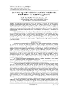
4 Design and implementation of Power Factor Correction Power Factor is a parameter that gives the amount of (PFC) using a Digital Signal Controller (DSC). The working Power used by any system in terms of the total software implementation of PFC using the 16-bit fixed apparent Power . Power Factor becomes an important point dsPIC DSC is explained in detail. The measurable quantity because it often results in discretization of the error compensators, along with a significant economic savings. design example is covered as well. In conclusion, some laboratory test results and waveforms are presented to Typical waveforms of current with and without PFC are validate the digital implementation of the PFC shown in Figure 1. converter . 2007 Microchip Technology Inc. DS01106A-page 1. AN1106.
5 FIGURE 1: CURRENT WAVEFORMS WITH AND WITHOUT PFC. Input Voltage 0. DC Bus Output Voltage Without Input Current PFC. 0. DC Bus Output Voltage With PFC. Input Current These waveforms illustrate that PFC can improve the The remaining Power that is lost as Reactive Power in input current drawn from the mains supply and reduce the system is due to two reasons: the DC bus voltage ripple. Phase shift of current with respect to voltage, The objective of PFC is to make the input to a Power resulting in displacement supply look like a simple resistor. This allows the Power Harmonic content present in current, resulting in distribution system to operate more efficiently, reducing distortion energy consumption. These two factors define Displacement Factor and The Power Factor is equal to Real Power divided by Distortion Factor , which provide the Power Factor as Apparent Power , as shown in Equation 1.
6 Shown in Equation 2. The amount of displacement between the voltage and current indicates the degree EQUATION 1: Power Factor to which the load is reactive. Power Factor = Real Power / Volt x Ampere When the ratio deviates from a constant, the input contains phase displacement, harmonic distortion or both, and either one degrades the Power Factor . 2007 Microchip Technology Inc. DS01106A-page 2. AN1106. EQUATION 2: Power Factor . Power Factor = Displacement Factor x Distortion Factor 1. PowerFactor = cos ---------------------------------------- ---------------------------- cos . - = ---------------------------- 2 2. 1 + ( I2 I1 ) 2 + ( I3 I1 ) + 1 + THD. Displacement Factor Distortion Factor 2. THD = 1 + ( I2 I1 ) 2 + ( I3 I1 ) + . where: cos = Displacement Factor of the voltage and current THD = Total Harmonic Distortion I1 = Current drawn from the supply at fundamental frequency I2 = Current drawn from the supply at double the fundamental frequency and so on Harmonic Content PFC aims at improving the displacement and distortion factors to derive maximum Real Power from the supply.
7 Current harmonics are sinusoidal waves that are This is done by reducing the losses that occur in the integral multiples of the fundamental wave. They system due to the presence of reactive elements, appear as continuous, steady-state disturbances on resulting in the improvement of Power quality and the electrical network. Harmonics are altogether overall efficiency of the system. different from line disturbances, which occur as transient distortions due to Power surges. When the Power converter is fed from a voltage source, and by making the Power converter appear as a linear SOURCES OF CURRENT HARMONICS resistance to the supply voltage, the input current wave shape can be made to follow the input voltage wave Some of the prominent sources that cause current shape. For example, if the input voltage (V) is in the harmonics distortion are: form of a sine wave, input current (I) is the same as that Power Electronic Equipment (rectifiers, UPS shown in Figure 2.)
8 Systems, variable frequency drives, state converters, thyristor systems, switch mode Power FIGURE 2: supplies, SCR controlled systems, etc.). Linear Resistor Auxiliary Equipment (welding machines, arc I. furnaces, mercury vapor lamps, etc.). Saturable Inductive Equipment (generators, motors, transformers, etc.) V R. PROBLEMS CREATED BY CURRENT. HARMONICS. Problems created by current harmonics include, but are not limited to: Erroneous operation of control system V. components V (t) I. Damage to sensitive electronic equipment I (t). Nuisance tripping of circuit breakers and blowing fuses Excessive overheating of capacitors, transformers, motors, lighting ballasts and other electrical equipment Interference with neighboring electronic t equipment To reduce these problems of current harmonics, the current drawn from the input needs to be shaped similar to that of voltage wave profile.
9 The Total Harmonic Distortion (THD) is shown in Equation 2. 2007 Microchip Technology Inc. DS01106A-page 3. AN1106. HOW TO MAKE THE Power FIGURE 4: SUDDEN CHANGE IN. converter LOOK RESISTIVE VOLTAGE. Despite having reactive passive elements like C. + - inductors, capacitors and active switching elements like MOSFETs and IGBTs, how can we make the converter appear to be resistive to the supply voltage? Closed The answer to this question lies in the fact that PFC is a low-frequency requirement. Therefore, the converter need not be resistive at all frequencies, provided a V. filtering mechanism exists to remove the high- frequency ripples. Active PFC must control both the input current and the The basic elements present in a converter are an output voltage. The current is shaped by the rectified inductor (L) and a capacitor (C), which are zero order line voltage so that the input to the converter appears elements.
10 This means that these elements cannot to be resistive. The output voltage is controlled by store energy in a single switching cycle due to their changing the average amplitude of the current fundamental properties: programming signal. An inductor cannot take a sudden change in Figure 3 and Figure 4 show the two fundamental current. This makes it a cut set with an open properties that lead to the following conclusions: switch and a periodic current source, as shown in The two elements, inductor and capacitor, can be Figure 3. considered to be resistive in the low frequency A capacitor cannot take a sudden change in range. voltage. This makes it a closed circuit with a The current through the inductor can be closed switch and a periodic voltage source, as programmed in such a way that it follows the supply shown in Figure 4.