Transcription of Power MOSFET - Vishay Intertechnology
1 Document Number: 91054 C, 21-Mar-111 This datasheet is subject to change without PRODUCT DESCRIBED HEREIN AND THIS DATASHEET ARE SUBJECT TO SPECIFIC DISCLAIMERS, SET FORTH AT MOSFETIRF740, SiHF740 Vishay Siliconix FEATURES Dynamic dV/dt Rating Repetitive Avalanche Rated Fast Switching Ease of Paralleling Simple Drive Requirements Compliant to RoHS Directive 2002/95/ECDESCRIPTIONT hird generation Power mosfets from Vishay provide thedesigner with the best combination of fast switching,ruggedized device design, low on-resistance andcost-effectiveness.
2 The TO-220AB package is universally preferred for allcommercial-industrial applications at Power dissipationlevels to approximately 50 W. The low thermal resistanceand low package cost of the TO-220AB contribute to itswide acceptance throughout the Repetitive rating; pulse width limited by maximum junction temperature (see fig. 11).b. VDD = 50 V, starting TJ = 25 C, L = mH, Rg = 25 , IAS = 10 A (see fig. 12).c. ISD 10 A, dI/dt 120 A/ s, VDD VDS, TJ 150 mm from SUMMARYVDS (V)400 RDS(on) ( )VGS = 10 V (Max.) (nC)63 Qgs (nC) (nC)32 ConfigurationSingleN-Channel MOSFET GDSTO-220 ABGDSA vailableRoHS*COMPLIANTORDERING INFORMATIONP ackageTO-220 ABLead (Pb)-freeIRF740 PbFSiHF740-E3 SnPbIRF740 SiHF740 ABSOLUTE MAXIMUM RATINGS (TC = 25 C, unless otherwise noted)
3 PARAMETER SYMBOLLIMITUNITD rain-Source VoltageVDS400 VGate-Source VoltageVGS 20 Continuous Drain CurrentVGS at 10 VTC = 25 C ID10 ATC = 100 C Drain CurrentaIDM 40 Linear Derating C Single Pulse Avalanche EnergybEAS 520mJ Repetitive Avalanche CurrentaIAR 10A Repetitive Avalanche EnergyaEAR13mJ Maximum Power DissipationTC = 25 C PD125W Peak Diode Recovery dV/dtcdV/dt Operating Junction and Storage Temperature RangeTJ, Tstg- 55 to + 150 C Soldering Recommendations (Peak Temperature)for 10 s300dMounting Torque6-32 or M3 screw10 lbf m* Pb containing terminations are not RoHS compliant, exemptions may apply Document Number: 910542S11-0507-Rev.
4 C, 21-Mar-11 This datasheet is subject to change without PRODUCT DESCRIBED HEREIN AND THIS DATASHEET ARE SUBJECT TO SPECIFIC DISCLAIMERS, SET FORTH AT , SiHF740 Vishay Siliconix Notesa. Repetitive rating; pulse width limited by maximum junction temperature (see fig. 11).b. Pulse width 300 s; duty cycle 2 %.THERMAL RESISTANCE RATINGSPARAMETER Junction-to-AmbientRthJA-62 C/WCase-to-Sink, Flat, Greased Junction-to-Case (Drain) (TJ = 25 C, unless otherwise noted)PARAMETER SYMBOLTEST CONDITIONS Breakdown Voltage VDS VGS = 0 V, ID = 250 A 400--V VDS Temperature Coefficient VDS/TJ Reference to 25 C, ID = 1 mA C Gate-Source Threshold Voltage VGS(th)
5 VDS = VGS, ID = 250 A Gate-Source Leakage IGSS VGS = 20 V-- 100nA Zero Gate Voltage Drain Current IDSS VDS = 400 V, VGS = 0 V --25 A VDS = 320 V, VGS = 0 V, TJ = 125 C --250 Drain-Source On-State Resistance RDS(on) VGS = 10 VID = Forward Transconductance gfs VDS = 50 V, ID = DynamicInput Capacitance Ciss VGS = 0 V,VDS = 25 V, f = MHz, see fig. 5 -1400-pFOutput Capacitance Coss -330-Reverse Transfer Capacitance Crss -120-Total Gate Charge Qg VGS = 10 V ID = 10 A, VDS = 320 V,see fig.
6 6 and 13b--63nC Gate-Source Charge Qgs ChargeQgd --32 Turn-On Delay Time td(on) VDD = 200 V, ID = 10 A Rg = , RD = 20 , see fig. 10b-14-nsRise Timetr -27-Turn-Off Delay Time td(off) -50-Fall Time tf -24-Internal Drain Inductance LD Between lead,6 mm ( ") from package and center of die contact Internal Source Body Diode CharacteristicsContinuous Source-Drain Diode Current ISMOSFET symbolshowing the integral reversep - n junction diode--10 APulsed Diode Forward CurrentaISM--40 Body Diode VoltageVSDTJ = 25 C, IS = 10 A, VGS = 0 Diode Reverse Recovery TimetrrTJ = 25 C, IF = 10 A, dI/dt = 100 A/ sb-370790nsBody Diode Reverse Recovery CForward Turn-On TimetonIntrinsic turn-on time is negligible (turn-on is dominated by LS and LD)DSGSDG Document Number.
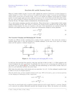
7 91054 C, 21-Mar-113 This datasheet is subject to change without PRODUCT DESCRIBED HEREIN AND THIS DATASHEET ARE SUBJECT TO SPECIFIC DISCLAIMERS, SET FORTH AT , SiHF740 Vishay Siliconix TYPICAL CHARACTERISTICS (25 C, unless otherwise noted)Fig. 1 - Typical Output Characteristics, TC = 25 CFig. 2 - Typical Output Characteristics, TC = 150 CFig. 3 - Typical Transfer CharacteristicsFig. 4 - Normalized On-Resistance vs. TemperatureVDS, Drain-to-Source Voltage (V)ID, Drain Current (A)91054_01 BottomTo pVGS15 V10 V20 s Pulse WidthTC = 25 VBottomTo pVGS15 V10 V20 s Pulse WidthTC = 150 C10110010-1100101 VDS, Drain-to-Source Voltage (V)ID, Drain Current (A)20 s Pulse WidthVDS = 50 V25 C150 C91054_0310110010-1ID, Drain Current (A)VGS, Gate-to-Source Voltage (V)56789104ID= 10 AVGS= 10 60 - 40 - 20 020 40 60 80 100 120 140 160TJ, Junction Temperature ( C)RDS(on), Drain-to-Source On Resistance(Normalized) Document Number: 910544S11-0507-Rev.
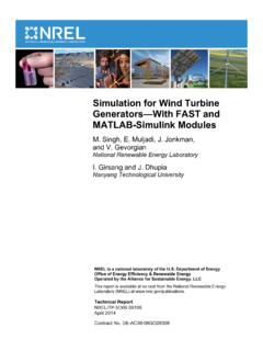
8 C, 21-Mar-11 This datasheet is subject to change without PRODUCT DESCRIBED HEREIN AND THIS DATASHEET ARE SUBJECT TO SPECIFIC DISCLAIMERS, SET FORTH AT , SiHF740 Vishay Siliconix Fig. 5 - Typical Capacitance vs. Drain-to-Source VoltageFig. 6 - Typical Gate Charge vs. Drain-to-Source VoltageFig. 7 - Typical Source-Drain Diode Forward VoltageFig. 8 - Maximum Safe Operating AreaCissCrssCossVGS= 0 V, f = 1 MHzCiss = Cgs + Cgd, Cds ShortedCrss = CgdCoss = Cds + Cgd91054_0525002000150010000500100101 Capacitance (pF)VDS, Drain-to-Source Voltage (V)91054_06ID = 10 AVDS = 200 VFor test circuitsee figure 13 VDS = 80 VVDS = 320 VQG, Total Gate Charge (nC)VGS, Gate-to-Source Voltage (V)2016128040157560453091054_07101100 VSD, Source-to-Drain Voltage (V)ISD, Reverse Drain Current (A) C150 CVGS = 0 V10-191054_0810 s100 s1 ms10 msOperation in this area limitedby RDS(on)TC = 25 CTJ = 150 CSingle PulseID, Drain Current (A)
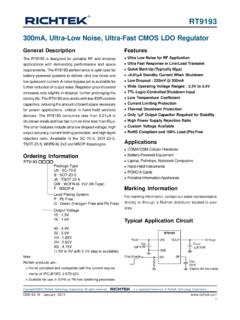
9 103251252525 VDS, Drain-to-Source Voltage (V) Document Number: 91054 C, 21-Mar-115 This datasheet is subject to change without PRODUCT DESCRIBED HEREIN AND THIS DATASHEET ARE SUBJECT TO SPECIFIC DISCLAIMERS, SET FORTH AT , SiHF740 Vishay Siliconix Fig. 9 - Maximum Drain Current vs. Case TemperatureFig. 10a - Switching Time Test CircuitFig. 10b - Switching Time WaveformsFig. 11 - Maximum Effective transient Thermal Impedance, Junction-to-Case91054_09ID, Drain Current (A)TC, Case Temperature ( C)0468102515012510075502 Pulse width 1 sDuty factor % V+-VDSVDDVDS90 %10 %VGStd(on)trtd(off)tf91054_110 - Pulse(Thermal Response)PDMt1t2 Notes:1.
10 Duty Factor, D = t1/t22. Peak Tj = PDM x ZthJC + Response (ZthJC) , Rectangular Pulse Duration (S) Document Number: 910546S11-0507-Rev. C, 21-Mar-11 This datasheet is subject to change without PRODUCT DESCRIBED HEREIN AND THIS DATASHEET ARE SUBJECT TO SPECIFIC DISCLAIMERS, SET FORTH AT , SiHF740 Vishay Siliconix Fig. 12a - Unclamped Inductive Test CircuitFig. 12b - Unclamped Inductive WaveformsFig. 12c - Maximum Avalanche Energy vs. Drain CurrentFig. 13a - Basic Gate Charge WaveformFig. 13b - Gate Charge Test +-VDD10 VVar y tp to obtainrequired IASIASVDSVDDVDStp91054_12cBottomTo A 10 AVDD = 50 V120002004006008001000251501251007550 Starting TJ, Junction Temperature ( C)EAS, Single Pulse Energy (mJ)QGSQGDQGVGC harge10 F50 k 12 VCurrent regulatorCurrent sampling resistorsSame type as +- Document Number.