Transcription of Precision Instrumentation Amplifier AD8221 - Analog Devices
1 Precision Instrumentation Amplifier AD8221 Rev. C Information furnished by Analog Devices is believed to be accurate and reliable. However, no responsibility is assumed by Analog Devices for its use, nor for any infringements of patents or other rights of third parties that may result from its use. Specifications subject to change without notice. No license is granted by implication or otherwise under any patent or patent rights of Analog Devices . Trademarks and registered trademarks are the property of their respective owners.
2 One Technology Way, Box 9106, Norwood, MA 02062-9106, Tel: Fax: 2003 2011 Analog Devices , Inc. All rights reserved. FEATURES Easy to use Available in space-saving MSOP Gain set with 1 external resistor (gain range 1 to 1000) Wide power supply range: V to 18 V Temperature range for specified performance: 40 C to +85 C Operational up to 125 C1 Excellent AC specifications 80 dB minimum CMRR to 10 kHz (G = 1) 825 kHz, 3 dB bandwidth (G = 1) 2 V/ s slew rate Low noise 8 nV/ Hz, @ 1 kHz, maximum input voltage noise V p-p input noise ( Hz to 10 Hz) High accuracy dc performance (AD8221BR) 90 dB minimum CMRR (G = 1)
3 25 V maximum input offset voltage V/ C maximum input offset drift nA maximum input bias current APPLICATIONS Weigh scales Industrial process controls Bridge amplifiers Precision data acquisition systems Medical Instrumentation Strain gages Transducer interfaces GENERAL DESCRIPTION The AD8221 is a gain programmable, high performance Instrumentation Amplifier that delivers the industry s highest CMRR over frequency in its class. The CMRR of Instrumentation amplifiers on the market today falls off at 200 Hz. In contrast, the AD8221 maintains a minimum CMRR of 80 dB to 10 kHz for all grades at G = 1.
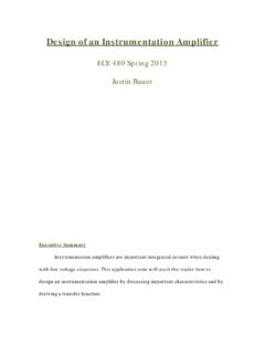
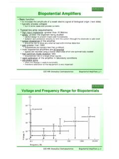
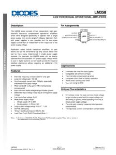
4 High CMRR over frequency allows the AD8221 to reject wideband interference and line harmonics, greatly simplifying filter requirements. Possible applications include Precision data acquisition, biomedical analysis, and aerospace Instrumentation . CONNECTION DIAGRAM 87651234 INRGRG+VSVOUTREF VS+INTOP VIEWAD822103149-001 Figure 1. 405060708090 CMRR (dB)100110120 FREQUENCY (Hz)100101k10k100k03149-002AD8221 COMPETITOR 1 COMPETITOR 2 Figure 2. Typical CMRR vs. Frequency for G = 1 Low voltage offset, low offset drift, low gain drift, high gain accuracy, and high CMRR make this part an excellent choice in applications that demand the best dc performance possible, such as bridge signal conditioning.
5 Programmable gain affords the user design flexibility. A single resistor sets the gain from 1 to 1000. The AD8221 operates on both single and dual supplies and is well suited for applications where 10 V input voltages are encountered. The AD8221 is available in a low cost 8-lead SOIC and 8-lead MSOP, both of which offer the industry s best performance. The MSOP requires half the board space of the SOIC, making it ideal for multichannel or space-constrained applications. Performance is specified over the entire industrial temperature range of 40 C to +85 C for all grades.
6 Furthermore, the AD8221 is operational from 40 C to +125 C1. 1 See Typical Performance Characteristics for expected operation from 85 C to 125 C. AD8221 Rev. C | Page 2 of 24 TABLE OF CONTENTS Features .. 1 Applications .. 1 General Description .. 1 Connection Diagram .. 1 Revision History .. 2 Specifications .. 3 Absolute Maximum Ratings .. 8 Thermal Characteristics .. 8 ESD Caution .. 8 Pin Configuration and Function Descriptions .. 9 Typical Performance Characteristics .. 10 Theory of Operation .. 17 Gain Selection .. 18 Layout.
7 18 Reference Terminal .. 19 Power Supply Regulation and Bypassing .. 19 Input Bias Current Return Path .. 19 Input Protection .. 19 RF Interference .. 20 Precision Strain Gage .. 20 Conditioning 10 V Signals for a +5 V Differential Input ADC .. 20 AC-Coupled Instrumentation Amplifier .. 21 Die Information .. 22 Outline Dimensions .. 23 Ordering Guide .. 24 REVISION HISTORY 3/11 Rev. B to Rev. C Added Pin Configuration and Function Descriptions Section .. 9 Added Die Information Section .. 22 Updated Outline Dimensions .. 23 Changes to Ordering Guide.
8 24 9/07 Rev. A to Rev. B Changes to Features .. 1 Changes to Table 1 Layout .. 3 Changes to Table 2 Layout .. 5 Changes to Figure 15 .. 11 Changes to Figures 32 .. 13 Changes to Figure 33, Figure 34, and Figure 35 .. 14 Updated Outline Dimensions .. 21 Changes to Ordering Guide .. 22 11/03 Rev. 0 to Rev. A Changes to Features .. 1 Changes to Specifications Section .. 4 Changes to Theory of Operation Section .. 13 Changes to Gain Selection 14 10/03 Revision 0: Initial Version AD8221 Rev. C | Page 3 of 24 SPECIFICATIONS VS = 15 V, VREF = 0 V, TA = 25 C, G = 1, RL = 2 k , unless otherwise noted.
9 Table 1. AR Grade BR Grade Parameter Conditions Min Typ Max Min Typ Max Unit COMMON-MODE REJECTION RATIO CMRR DC to 60 Hz with 1 k Source Imbalance VCM = 10 V to +10 V G = 1 80 90 dB G = 10 100 110 dB G = 100 120 130 dB G = 1000 130 140 dB CMRR at 10 kHz VCM = 10 V to +10 V G = 1 80 80 dB G = 10 90 100 dB G = 100 100 110 dB G = 1000 100 110 dB NOISE RTI noise = eNI2 + (eNO/G)2 Voltage Noise, 1 kHz Input Voltage Noise, eNI VIN+, VIN , VREF = 0 8 8 nV/ Hz Output Voltage Noise, eNO 75 75 nV/ Hz RTI f = Hz to 10 Hz G = 1 2 2 V p-p G = 10 V p-p G = 100 to 1000 V p-p Current Noise f = 1 kHz 40 40 fA/ Hz f = Hz to 10 Hz 6 6 pA p-p VOLTAGE OFFSET1 Input Offset, VOSI VS = 5 V to 15 V 60 25 V Over Temperature T = 40 C to +85 C 86 45 V Average TC V/ C Output Offset.
10 VOSO VS = 5 V to 15 V 300 200 V Over Temperature T = 40 C to +85 C mV Average TC 6 5 V/ C Offset RTI vs. Supply (PSR) VS = V to 18 V G = 1 90 110 94 110 dB G = 10 110 120 114 130 dB G = 100 124 130 130 140 dB G = 1000 130 140 140 150 dB INPUT CURRENT Input Bias Current nA Over Temperature T = 40 C to +85 C 1 nA Average TC 1 1 pA/ C Input Offset Current nA Over Temperature T = 40 C to +85 C nA Average TC 1 1 pA/ C REFERENCE INPUT RIN 20 20 k IIN VIN+, VIN , VREF = 0 50 60 50 60 A Voltage Range VS +VS VS +VS V Gain to Output 1 1 V/V AD8221 Rev.