Transcription of SGTL5000, Low Power Stereo Codec with Headphone Amp - …
1 Document Number: SGTL5000 Rev. 7, 1/2022 NXP Semiconductors Data Sheet: Technical Data 2021 NXP Power Stereo Codec with Headphone AmpThe SGTL5000 is a Low Power Stereo Codec with Headphone Amp from NXP, and is designed to provide a complete audio solution for products needing LINEIN, MIC_IN, LINEOUT, Headphone -out, and digital I/O. Deriving it s architecture from best in class, NXP integrated products that are currently on the market. The SGTL5000 is able to achieve ultra low Power with very high performance and functionality, all in one of the smallest footprints available. Target markets include media players, navigation devices, smart phones, tablets, medical equipment, exercise equipment, consumer audio equipment, etc.
2 Features such as capless Headphone design and an internal PLL help lower overall system Inputs Stereo LINEIN - Support for external analog input Stereo LINEIN - Codec bypass for low Power MIC bias provided Programmable MIC gain ADC - 85 dB SNR (-60 dB input ) and -73 dB THD+N (VDDA = V)Analog Outputs HP Output - Capless design HP Output - mW max, kHz sine into 16 load at V HP Output - 100 dB SNR (-60 dB input ) and -80 dB THD+N (VDDA = V, 16 load, DAC to Headphone ) LINEOUT - 100 dB SNR (-60 dB input ) and -85 dB THD+N (VDDIO = V)Digital I/O I2S port to allow routing to Application ProcessorIntegrated Digital Processing NXP surround, NXP bass, tone control/ parametric equalizer/graphic equalizer clocking/control PLL allows input of an MHz to 27 MHz system clock - standard audio clocks are derived from PLLP ower Supplies Designed to operate from to volts Figure 1.
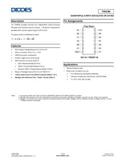
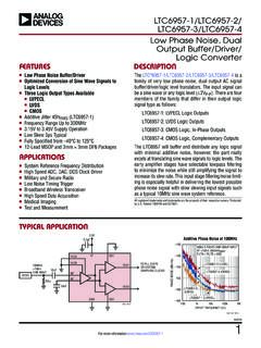
3 SGTL5000 Simplified Application DiagramAUDIO CODECSGTL5000 ORDERING INFORMATIOND evice Temperature Range (TA)PackageSGTL5000 XNLA3/R2-40 to 85 C20 Sawn QFNSGTL5000 XNAA3/R2(1) 32 Punch QFNSGTL5000 XNBA3/R232 Sawn will undergo End-of-Life / Product Discontinuation by end of Q1 QFNSGTL5000 XNLA3PB-FREE98 ASA01814D32-PIN QFNSGTL5000 XNBA3PB-FREE98 ARE10739D32-PIN QFNSGTL5000 XNAA3I2 SInterfaceHeadphone /Line Outw/ volumeAudio SwitchADCDACI2 S_D OU TI2S_DINI2S_SCLKI2S_LRCLKLINEOUT_RLINEOU T_LHP_RHP_LI2C/SPI ControlSYS_MCLKPLLA pplication ProcessorHeadphoneSpeaker Amp/Docking Station/FMTXA udioProcessingAnalog In( Stereo Line In, MIC)LINEIN_RLINEIN_LMIC_INMIC_BIASMP3/FM InputMIC IN /Speech RecognitionI2 SInterfaceHeadphone /Line Outw/ volumeAudio SwitchADCDACI2 S_D OU TI2S_DINI2S_SCLKI2S_LRCLKLINEOUT_RLINEOU T_LHP_RHP_LI2C/SPI ControlSYS_MCLKPLLA pplication ProcessorHeadphoneSpeaker Amp/Docking Station/FMTXA udioProcessingAnalog In( Stereo Line In, MIC)LINEIN_RLINEIN_LMIC_INMIC_BIASMP3/FM InputMIC IN /Speech RecognitionNote: SPI is not supported in the mm x mm 20-pin QFN package 2 NXP SemiconductorsSGTL5000 INTERNAL BLOCK DIAGRAMINTERNAL BLOCK DIAGRAM Figure 2.
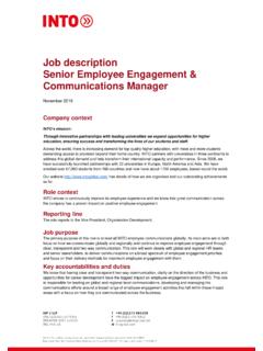
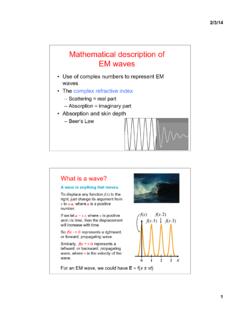
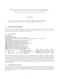
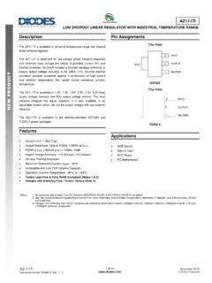
4 SGTL5000 Simplified Internal Block DiagramMIC GAIN(0dB, 20dB, 30dB, 40dB )MIC_INAudio SwitchI2S_DINADCI2S_DOUTMix +6dBTone Control /GEQ/PEQ +12 dBBass Enhancement +6dBSurroundAVC+12dBDACDAC Volume Control-90dB to 0dBHeadphone Volume Control-52dB to +12dB(CHIP_ANA_HP_CTRL)HP_OUTA nalog GainDigital GainAnalog Gain(0 to dB)Only Gain is shown for the Digital Audio Processing blocks. For complete description please see Digital Audio Processing Out Volume Control(CHIP_LINE_OUT_VOL)LINEOUTLINE_IN NXP Semiconductors3 SGTL5000 PIN CONNECTIONSPIN CONNECTIONS Figure 3. SGTL5000 Pin Connections20 QFNT ransparent Top View32 QFNT ransparent Top View1234567891011121314151617181920HP_RH P_VGNDVDDAHP_LVAGLINEOUT_RLINEOUT_LLINEI N_RLINEIN_LMICMIC_BIASVDDIOSYS_MCLKI2S_L RCLKI2S_SCLKI2S_DOUTI2S_DINCTRL_DATACTRL _CLKVDDDGND32 QFNT ransparent Top View123456789 101112 1314151617181920212223242526272829303132 LINEOUT_RLINEOUT_LLINEIN_RLINEIN_LMICMIC _BIASCPFILTNCI2S_LRCLKI2S_SCLKI2S_DOUTI2 S_DINCTRL_DATACTRL_CLKVDDDHP_RHP_VGNDVDD AHP_LNCGNDAGNDNCNCCTRL_MODECTRL_ADR0_CSG NDSYS_MCLKVDDIOVAGNCNCGNDSGTL5000 XNLA3 SGTL5000 XNAA3 SGTL5000 XNBA3 4 NXP SemiconductorsSGTL5000 PIN CONNECTIONSA functional description can be found in Functional Description, beginning on page 13.
5 Table 1. SGTL5000 Pin Definitions 20 Pin QFN32 Pin QFNPin NamePin FunctionFormal NameDefinition12HP_RAnalogRight Headphone output24HP_VGNDA nalogHeadphone virtual groundDo not connect HP_VGND to system ground, even when unused. This is a virtual ground (DC voltage) that should never connect to an actual 0 Volt ground . Use the widest, shortest trace possible for the voltage46HP_LAnalogLeft Headphone output-7 AGNDA nalog GroundGround-8, 9, 17, 19, 22, 28 NCNo Connect510 VAGA nalogDAC VAG filter611 LINEOUT_RAnalogRight LINEOUT712 LINEOUT_LAnalogLeft LINEOUT813 LINEIN_RAnalogRight LINEIN914 LINEIN_LAnalogLeft LINEIN1015 MICA nalogMicrophone input1116 MIC_BIASA nalogMic bias 18 CPFILTA nalogCharge Pump FilterThe CPFILT cap value is F.
6 If both VDDIO and VDDA are V, the CPFILT pin must be connected to a F cap to GND. If either is > V, the CPFILT cap MUST NOT be I/O voltage1321 SYS_MCLKD igitalSystem master clock1423I2S_LRCLKD igitalI2S frame clock1524I2S_SCLKD igitalI2S bit clock1625I2S_DOUTD igitalI2S data output1726I2S_DIND igitalI2S data input1827 CTRL_DATAD igitalI2C Mode: Serial Data (SDA); SPI Mode: Serial Data input (MOSI)1929 CTRL_CLKD igitalI2C Mode: Serial Clock (SCL); SPI Mode: Serial Clock (SCK)2030 VDDDD igitalDigital voltageFor new designs, connect VDDD to an external voltage source and to a F capacitor to Mode: I2C Address Select 0; SPI Mode: SPI Chip Select NXP Semiconductors5 SGTL5000 PIN CONNECTIONS-32 CTRL_MODED igitalMode select for I2C or SPI.
7 When pulled low the control mode is I2C, when pulled high the control mode is SPIPAD1, 3, 4, PADGNDG roundGroundThe PAD must be soldered to the ground pins of the chip, VAG ground, and all analog inputs/outputs to a single point, then to the ground 1. SGTL5000 Pin Definitions (continued)20 Pin QFN 32 Pin QFNPin NamePin FunctionFormal NameDefinition 6 NXP SemiconductorsSGTL5000 ELECTRICAL CHARACTERISTICSMAXIMUM RATINGSELECTRICAL CHARACTERISTICSMAXIMUM RATINGST able 2. Maximum RatingsExceeding the absolute maximum ratings shown in the following table could cause permanent damage to the part and is not recommended. Normal operation is not guaranteed at the absolute maximum ratings, and extended exposure could affect long term RATINGS Maximum Digital Digital I/O Analog Supply voltage on any digital to VDDIO+ voltage on any analog to VDDA+ RATINGSS torage TemperatureTSTG- 55 to 125 COperating TemperatureAmbientTA- 40 to 85 CTable 3.
8 Recommended Operating ConditionsRatingsSymbolValueUnitDigital Voltage (If supplied externally). External VDDD connection required for new to I/O to Supply to NXP Semiconductors7 SGTL5000 ELECTRICAL CHARACTERISTICSMAXIMUM RATINGST able 4. input /Output Electrical Characteristics Test Conditions unless otherwise noted: VDDIO = V, VDDA = V, TA = 25 C, Slave mode, fS = 48 kHz, MCLK = 256 fS, 24 bit input , kHz input Level ( V VDDA) input Level ( V VDDA) input Level ( V VDDA) input Level ( V VDDA) Output level0 dBFS at kHz 12S input , V LINEOUT supply (normally VDDIO), 10 k Output level0 dBFS at kHz 12S input , V LINEOUT supply (normally VDDIO), 10 k input Impedance-29-k MIC input LINEOUT Output Impedance-320- LINEOUT Load10--k HP ( Headphone ) Load16-- SYS_MCLK input Voltage + Rise/Fall 8 NXP SemiconductorsSGTL5000 ELECTRICAL CHARACTERISTICSSTATIC ELECTRICAL CHARACTERISTICSSTATIC ELECTRICAL CHARACTERISTICS Table 5.
9 Audio Performance 1 Test Conditions unless otherwise noted: VDDIO = V, VDDA = V, TA = 25 C, Slave mode, fS = 48 kHz, MCLK = 256 fS, 24 bit inputCharacteristicSymbolMinTypMaxUnitAU DIO PERFORMANCELINEIN input input Impedance (at kHz)-29-k LINEIN -> ADC -> I2S OUTSNR (-60 dB input )-85-dBTHD+N--70-dBFrequency Response- Separation-79-dBLINEIN -> HEADPHONE_LINEOUT ( Codec BYPASS MODE)SNR (-60 dB input )-98-dBTHD+N (10 k load)--87-dBTHD+N (16 load)--87-dBFrequency Response- Separation (at kHz)82dBI2S IN -> DAC -> LINEOUTO utput (-60 dB input )-95-dBTHD+N--85-dBFrequency Response- IN -> DAC -> Headphone OUT - 16 LOADO utput Power -17-mWSNR (-60 dB input )-100-dBTHD+N--80-dBFrequency Response- IN -> DAC -> Headphone OUT - 32 LOADO utput Power -10-mWSNR (-60 dB input )-95-dBTHD+N--86-dBFrequency Response- IN -> DAC -> Headphone OUT - 10 K LOADSNR (-60 dB input )-96-dBTHD+N--84-dBFrequency Response- (200 mVp-p at kHz on VDDA)-85-dB NXP Semiconductors9 SGTL5000 ELECTRICAL CHARACTERISTICSSTATIC ELECTRICAL CHARACTERISTICS Table 6.
10 Audio Performance 2 Test Conditions unless otherwise noted: VDDIO = V, VDDA = V, TA = 25 C, Slave mode, fS = 48 kHz, MCLK = 256 fS, 24 bit input . ADC tests were conducted with BIAS_CTRL = , all other tests conducted with BIAS_CTRL = -50%.CharacteristicSymbolMinTypMaxUnitAU DIO PERFORMANCELINEIN input input Impedance (at kHz)-29-k LINEIN -> ADC -> I2S OUTSNR (-60 dB input )-90-dBTHD+N--72-dBFrequency Response- Separation-80-dBLINEIN -> HEADPHONE_LINEOUT ( Codec BYPASS MODE)SNR (-60 dB input )-102-dBTHD+N (10 k load)--89-dBTHD+N (16 load)--87-dBFrequency Response- Separation (at kHz)81dBI2S IN -> DAC -> LINEOUTO utput (-60 dB input )-100-dBTHD+N--85-dBFrequency Response- IN -> DAC -> Headphone OUT - 16 LOADO utput Power -58-mWSNR (-60 dB input )-98-dBTHD+N--86-dBFrequency Response- IN -> DAC -> Headphone OUT - 32 LOADO utput Power -30-mWSNR (-60 dB input )