Transcription of LTC6957-1/LTC6957-2/LTC6957-3/LTC6957-4 - Low Phase …
1 LTC6957-1/LTC6957-2/LTC6957-3/LTC6957-41 6957fbFor more information APPLICATION FEATURESDESCRIPTIONLow Phase Noise, Dual Output Buffer/Driver/ Logic ConverterThe LT C 6957-1/LTC6957-2/LTC6957-3/LTC6957-4 is a family of very low Phase noise, dual output AC signal buffer/driver/logic level translators. The input signal can be a sine wave or any logic level ( 2VP-P). There are four members of the family that differ in their output logic signal type as follows: LTC6957-1: LVPECL Logic Outputs LTC6957-2: LVDS Logic Outputs LTC6957-3: CMOS Logic, In- Phase Outputs LTC6957-4: CMOS Logic, Complementary OutputsThe LTC6957 will buffer and distribute any logic signal with minimal additive noise, however, the part really excels at translating sine wave signals to logic levels.
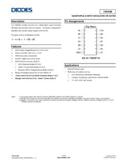
2 The early amplifier stages have selectable lowpass filtering to minimize the noise while still amplifying the signal to increase its slew rate. This input stage filtering/noise limit-ing is especially helpful in delivering the lowest possible Phase noise signal with slow slewing input signals such as a typical 10 MHz sine wave system registered trademarks and trademarks are the property of their respective owners. Protected by Patents 7969189 and Phase Noise at 100 MHzAPPLICATIONS nLow Phase Noise Buffer/Driver nOptimized Conversion of Sine Wave Signals to Logic Levels nThree Logic Output Types Available nLVPECL nLVDS nCMOS nAdditive Jitter 45fsRMS (LTC6957-1)
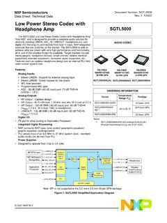
3 NFrequency Range Up to 300 MHz to Supply Operation nLow Skew 3ps Typical nFully Specified from 40 C to 125 C n12-Lead MSOP and 3mm 3mm DFN Packages nSystem Reference Frequency Distribution nHigh Speed ADC, DAC, DDS Clock Driver nMilitary and Secure Radio nLow Noise Timing Trigger nBroadband Wireless Transceiver nHigh Speed Data Acquisition nMedical Imaging nTest and MeasurementOFFSET FREQUENCY (Hz)100 165 Phase NOISE (dBc/ Hz) 160 155 150 1401k10k100k69571234 TA01b 1451 MLTC6957-1 (LVPECL)LTC6957-4 (CMOS)LTC6957-3(CMOS)LTC6957-2 (LVDS)SINGLE-ENDED SINE WAVE INPUTAT +7dBm (500mVRMS)FILTA = FILTB = GND6957 TA01aSD1SD2V+GNDOUT2 OUT1 FILTAFILTB10nF50 100 MHz+7dBmSINE WAVE10nFIN IN+ PLL CHIPSOR SYSTEMSAMPLING FLTC6957-1/LTC6957-2/LTC6957-3/LTC6957-4 26957fbFor more information , LTC6957-2 LTC6957-3, LTC6957-4 TOP VIEWDD PACKAGE12-LEAD (3mm 3mm) PLASTIC DFN1211891045321SD1 OUT1+OUT1 OUT2 OUT2+SD2 FILTAV+IN+IN GNDFILTB6713 GND TJMAX = 150 C, JA = 58 C/W, JC = 10 C/W EXPOSED PAD (PIN 13) IS GND, MUST BE SOLDERED TO PCBTOP VIEWDD PACKAGE12-LEAD (3mm 3mm)
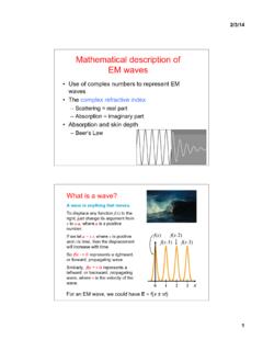
4 PLASTIC DFN1211891045321SD1 VDDOUT1 OUT2 GNDOUTSD2 FILTAV+IN+IN GNDFILTB6713 GND TJMAX = 150 C, JA = 58 C/W, JC = 10 C/W EXPOSED PAD (PIN 13) IS GND, MUST BE SOLDERED TO PCBLTC6957-1, LTC6957-2 LTC6957-3, LTC6957-4123456 FILTAV+IN+IN GNDFILTB121110987SD1 OUT1+OUT1 OUT2 OUT2+SD2 TOP VIEWMS PACKAGE12-LEAD PLASTIC MSOP TJMAX = 150 C, JA = 145 C/W123456 FILTAV+IN+IN GNDFILTB121110987SD1 VDDOUT1 OUT2 GNDOUTSD2 TOP VIEWMS PACKAGE12-LEAD PLASTIC MSOP TJMAX = 150 C, JA = 145 C/WABSOLUTE MAXIMUM RATINGSS upply Voltage (V+ or VDD) to GND .. Current (IN+, IN , FILTA, FILTB, SD1, SD2) (Note 2).
5 10mALTC6957-1 Output Current ..1mA , 30mALTC6957-2 Output Current .. 10mALTC6957-3, LTC6957-4 Output Current (Note 3) .. 30mA(Note 1)PIN CONFIGURATIONS pecified Temperature Range LTC6957I .. 40 C to 85 C LTC6957H .. 40 C to 125 CJunction Temperature ..150 CStorage Temperature Range .. 65 C to 150 CLead Temperature (for MSOP Soldering, 10sec) .. 300 CLTC6957-1/LTC6957-2/LTC6957-3/LTC6957-4 36957fbFor more information INFORMATIONLEAD FREE FINISHTAPE AND REELPART MARKING*PACKAGE DESCRIPTIONSPECIFIED TEMPERATURE RANGELTC6957 IDD-1#PBFLTC6957 IDD-1#TRPBFLFQJ12-Lead (3mm 3mm) Plastic DFN 40 C to 85 CLTC6957 IDD-2#PBFLTC6957 IDD-2#TRPBFLFQK12-Lead (3mm 3mm) Plastic DFN 40 C to 85 CLTC6957 IDD-3#PBFLTC6957 IDD-3#TRPBFLFQM12-Lead (3mm 3mm) Plastic DFN 40 C to 85 CLTC6957 IDD-4#PBFLTC6957 IDD-4#TRPBFLFQN12-Lead (3mm 3mm)
6 Plastic DFN 40 C to 85 CLTC6957 IMS-1#PBFLTC6957 IMS-1#TRPBF6957112-Lead Plastic MSOP 40 C to 85 CLTC6957 HMS-1#PBFLTC6957 HMS-1#TRPBF6957112-Lead Plastic MSOP 40 C to 125 CLTC6957 IMS-2#PBFLTC6957 IMS-2#TRPBF6957212-Lead Plastic MSOP 40 C to 85 CLTC6957 HMS-2#PBFLTC6957 HMS-2#TRPBF6957212-Lead Plastic MSOP 40 C to 125 CLTC6957 IMS-3#PBFLTC6957 IMS-3#TRPBF6957312-Lead Plastic MSOP 40 C to 85 CLTC6957 HMS-3#PBFLTC6957 HMS-3#TRPBF6957312-Lead Plastic MSOP 40 C to 125 CLTC6957 IMS-4#PBFLTC6957 IMS-4#TRPBF6957412-Lead Plastic MSOP 40 C to 85 CLTC6957 HMS-4#PBFLTC6957 HMS-4#TRPBF6957412-Lead Plastic MSOP 40 C to 125 CConsult LTC Marketing for parts specified with wider operating temperature ranges.
7 *The temperature grade is identified by a label on the shipping more information on lead free part marking, go to: For more information on tape and reel specifications, go to: Some packages are available in 500 unit reels through designated sales channels with #TRMPBF #orderinfoLTC6957-1/LTC6957-2/LTC6957-3/ LTC6957-446957fbFor more information CHARACTERISTICSSYMBOL PARAMETERCONDITIONSMINTYPMAXUNITSI nputs (IN , IN+)fINInput Frequency Rangel300 MHzVINSEI nput Signal Level Range, Signal Level Range, input Pulse WidthHigh or Voltage, IN+, IN Resistance, CINI nput Capacitance, Section Small Signal Bandwidth ( 3dB)
8 FILTB = L, FILTA = L FILTB = L, FILTA = H FILTB = H, FILTA = L FILTB = H, FILTA = H1200 500 160 50 MHz MHz MHz MHzOutputs (LVPECL)VOHO utput High VoltageLTC6957I LTC6957Hl lV+ V+ + V+ + V+ VVOLO utput Low VoltageLTC6957I LTC6957Hl lV+ V+ + V+ + V+ VVODO utput Differential Voltagel 660 810 965mVtrOutput Rise Time180pstfOutput Fall Time160pstPDPropagation DelayFILTB = L, FILTA = L FILTB = L, FILTA = H FILTB = H, FILTA = L FILTB = H, FILTA = Hl l l 4ns ns ns ns tPD/ TPropagation Delay Variation Over TemperatureFILTB = L, FILTA = L FILTB = L, FILTA = H FILTB = H, FILTA = L FILTB = H.
9 FILTA = Hl l l C ps/ C ps/ C ps/ C tPD/ VPropagation Delay Variation vs Supply VoltageFILTB = L, FILTA = Ll450ps/VtSKEWO utput Skew, Differential, CH1 to CH2l330pstMATCHO utput Matching (OUTx+ to OUTx )See Timing +V+ Operating Supply Voltage RangeRLOAD = 50 to (V+ 2V) Current Both Outputs Enabled (SD1 = SD2 = L) One Output Enabled (SD1 = L, SD2 = H or SD1 = H, SD2 = L) Both Outputs Disabled (SD1 = SD2 = H) Including Output Loads No Output Loads No Output Loads No Output Loads RLOAD = 50 to (V+ 2V), 4 l l l l 18 15 58 22 19 72 mA mA mA mAtENABLEO utput Enable Time, Other SDx = L40 stWAKEUPO utput Enable Time, Other SDx = H120 stDISABLEO utput Disable Time, Other SDx = L20 stSLEEPO utput Disable Time, Other SDx = H20 sThe l denotes the specifications which apply over the full operating temperature range, otherwise specifications are at TA = 25 C.
10 V+ = , SD1 = SD2 = , FILTA = FILTB = , RLOAD = 50 connected to , unless otherwise specified. All voltages are with respect to more information CHARACTERISTICSThe l denotes the specifications which apply over the full operating temperature range, otherwise specifications are at TA = 25 C. V+ = , SD1 = SD2 = , FILTA = FILTB = , RLOAD = 50 connected to , unless otherwise specified. All voltages are with respect to PARAMETERCONDITIONSMINTYPMAXUNITSD igital Logic InputsVIHHigh Level SD or FILT input VoltagelV+ Level SD or FILT input Current SD or FILT 10 AAdditive Phase Noise and JitterfIN = 300 MHz Sine Wave, 7dBm (FILTA = L, FILTB = L)