Transcription of The Power MOSFET Application Handbook Nexperia
1 3 The Power MOSFET Application HandbookDesign Engineer s GuideNexperiaManchester, United Kingdom4 The Power MOSFET Application HandbookDesign Engineer s GuideCopyright : 978-0-9934854-1-112NC: 9397 750 17686 All rights reserved. No part of this publication may be reproduced or distributed in any form or by any means without the prior written permission of the in the United Kingdom5 Andrew BerryAdam BrownBrian CliftonJamie DyerPhil EllisMark FangKeith HeppenstallChris HillKelly LawWayne LawsonKoji NishihataJim ParkinChristos PateropoulosPhil RutterContributors:67 Understanding Power MOSFET data sheet parametersPower MOSFET single-shot and repetitive avalanche ruggedness rating Using RC Thermal models LFPAK MOSFET thermal design part 1 LFPAK MOSFET thermal design part 2 Using Power mosfets in parallel Designing RC snubbersFailure signature of electrical overstress on Power MOSFETsAbbreviationsPower MOSFET frequently asked questions IndexLegal Information12345678989 Table of ContentsChapter 1: Understanding Power MOSFET data sheet parametersApplication Note.
2 Introduction Data sheet technical sections Product profile Pinning information Ordering information Limiting values Thermal characteristics Electrical characteristics Package outline Appendices Safe Operating Area (SOA) curves References 50 Chapter 2: Power MOSFET single-shot and repetitive avalanche ruggedness ratingApplication Note: Introduction Single-shot and repetitive avalanche definitions Understanding Power MOSFET single-shot avalanche events Single-shot UIS operation Single-shot avalanche ruggedness rating Understanding Power MOSFET repetitive avalanche events Repetitive UIS operation Temperature components Repetitive avalanche ruggedness rating Conclusion Examples Single-shot avalanche case Repetitive avalanche case References 6210 Chapter 3: Using RC Thermal ModelsApplication Note.
3 Introduction Thermal impedance Calculating junction temperature rise Association between Thermal and Electrical parameters Foster RC thermal models Thermal simulation examples Example 1 Example 2 Example 3 Discussions summary References 80 Chapter 4: LFPAK MOSFET thermal design - part 1 Application Note: Introduction The need for thermal analysis MOSFET Rth parameters and their limitations Aim of this chapter General approach to thermal analysis The use of thermal simulation software Simulation set-up PCB layout and stack-up A single LFPAK device Analysis 1: A single-layer PCB Analysis 2: 2-layer PCB Analysis 3: A 4-layer PCB part 1 Analysis 3: A 4-layer PCB part 2 Analysis 4: A 4-layer PCB with thermal vias part 1 Analysis 4: A 4-layer PCB with thermal vias part 2 summary : factors affecting the thermal performance of a single device Two LFPAK devices Analysis 5: A single-layer PCB Analysis 6: A 2-layer PCB Analysis 7: A generalized 4-layer PCB Analysis 8: A 4-layer PCB with thermal vias part 1 Analysis 8: A 4-layer PCB with thermal vias part 2 summary : factors affecting the thermal performance of two devices Four LFPAK devices Analysis 9: A single-layer PCB Analysis 10: A 2-layer PCB Analysis 11: A generalized 4-layer PCB Analysis 12: A 4-layer PCB with thermal vias part 1 Analysis 12: A 4-layer PCB with thermal vias part 2 summary .
4 Factors affecting the thermal performance of four devices summary 121 Chapter 5: LFPAK MOSFET thermal design - part 2 Application Note: Introduction The module model PCB characteristics Enclosure characteristics Axes naming convention The ambient environment Potential heat paths The influence of y-gap on Tj Black plastic enclosure; x- and z-gaps = zero Two more enclosure materials summary : the influence of y-gap on Tj Adding x- and z-gaps around the PCB The black plastic enclosure The polished aluminium enclosure The anodized aluminium enclosure The three enclosures side-by-side summary : adding x- and z-gaps around the PCB Encapsulating the PCB Partial encapsulation Full encapsulation summary : encapsulating the PCB Direct cooling through the enclosure Bottom-side cooling of the PCB Bottom-side cooling of the PCB, with encapsulation Top-side cooling of the PCB Top-side cooling of the PCB, with encapsulation summary .
5 Direct cooling through the enclosure Mounting the enclosure on a bulkhead Vertical orientation of the module Adding the bulkhead Results for the PCB mounted centrally in the module Results for the PCB with bottom-side cooling Results for the PCB with top-side cooling summary : mounting the enclosure on a bulkhead summary 168 Chapter 6: Using Power mosfets in parallelApplication Note: Introduction Static (DC) operation Worked examples for static operation MOSFET mounting for good thermal performance and Power sharing Power sharing in dynamic operation [pulse and Pulse Width Modulation (PWM) circuits] Partially enhanced (linear mode) Power sharing Gate drive considerations Should individual gate drivers be used for each MOSFET in the group?
6 MOSFET packaging considerations for paralleled groups Bare die (KGD) mosfets LFPAK mosfets Inductive energy dissipation in paralleled mosfets Avalanching - low side MOSFET group driving a high side inductive load Active clamping - high side MOSFET group driving a low side inductive load summary 188 Chapter 7: Designing RC snubbersApplication Note: Introduction Test circuit Determining CLK and LLK Designing the snubber - theory Designing the snubber - in practice summary Appendix A; determining CLK from Cadd, fRING0 and fRING1 198 Chapter 8: Failure signature of electrical overstress on Power mosfets Application Note: Introduction ESD - Machine Model ESD - Human body model Unclamped Inductive Switching (UIS) (Avalanche or Ruggedness)
7 Linear mode operation Over-current Appendices Machine model EOS of BUK9508-55A Machine model EOS of BUK9Y40-55B Machine model EOS of PSMN7R0-30YL Machine model EOS of PSMN011-30YL Human body model EOS of BUK9508-55A Human body model EOS of BUK9Y40-55B Human body model EOS of PSMN011-30YL Unclamped inductive switching EOS of BUK7L06-34 ARC Unclamped Inductive switching EOS of BUK9Y40-55B Unclamped inductive switching EOS of PSMN7R0-30YL Linear mode EOS of BUK7L06-34 ARC Linear mode EOS of BUK9Y40-55B Linear mode EOS of PSMN7R0-30YL Over-current EOS of BUK7L06-34 ARC Over-current EOS of PSMN7R0-30YL Tables Figures 234 Chapter 9: Power MOSFET frequently asked questionsApplication Note: Introduction Gate Thermal impedance (Zth) curves MOSFET body diode Safe operating area and linear mode operation Avalanche Ruggedness and Unclamped Inductive Switching (UIS) Capacitive dV/dt issues Package and mounting SPICE models MOSFET silicon technology Supply and availability EMC Leakage, breakdown and MOSFET characteristics MOSFET reliability 27715 Drawing on over 20 years of experience, the Power MOSFET Application Handbook brings together a comprehensive set of learning and reference materials relating to the use of Power mosfets in real world systems.
8 mosfets are used in a range of fields, from automotive and industrial to computing, mobile and Power supply, all of which have influenced the development of the material presented within this book is aimed at engineers from any industry who have need or interest in increasing their understanding of how to design with Power mosfets . The knowledge shared within this reference guide has been collected and developed through years of working with many different engineers from many different companies to solve real problems. Although MOSFET technology has moved on significantly in the last decades, many of the challenges facing designers remain the same. The goal of this book is to give insight into the sometimes confusing and complex behaviour of Power mosfets and provide engineers with the information necessary to solve common problems and avoid potential product information and recently published Application notes can be found at 1: Understanding Power MOSFET data sheet parametersApplication Note: AN11158 Chapter 1: Understanding Power MOSFET data sheet parameters18 This chapter explains the parameters and diagrams given in an Nexperia Power MOSFET data sheet.
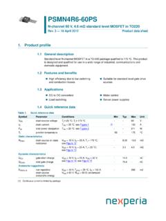
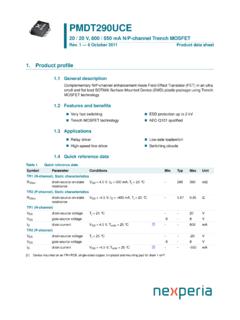
9 The goal is to help an engineer decide what device is most suitable for a particular is important to pay attention to the conditions for which the parameters are listed, as they can vary between suppliers. These conditions can affect the values of the parameters making it difficult to choose between different suppliers. Throughout this chapter, the data sheet for the BUK7Y12-55B is used as an example. BUK7Y12-55B is an automotive-qualified part in an SOT669 (LFPAK56) package, with a voltage rating of 55 layout of this data sheet is representative of the general arrangement of Nexperia Power MOSFET data sheets. Nexperia Power mosfets are designed with particular applications in mind. For example, switching charge is minimized where switching losses dominate, whereas on-resistance is minimized where conductive losses Product profile This section provides the overview of the device; giving the designer the key information regarding device suitability.
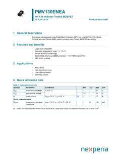
10 The general description describes the technology used; key features and example applications are quick reference data table contains more detailed information and the key parameters for the intended Application . An example of a quick reference data table is shown in Table 1 Quick reference data . Data sheet technical sectionsChapter 1: Understanding Power MOSFET data sheet parameters (AN11158)( Application Note AN11158)Chapter 1: Understanding Power MOSFET data sheet parameters 19 Chapter 1: Understanding Power MOSFET data sheet parameters (AN11158)Symbol ParameterConditionsMinTy pMax UnitVDSdrain-source voltageTj 25 oC; Tj 175 oC--55 VIDdrain currentVGS = 10 V; Tmb = 25 oC; Figure Power dissipationTmb = 25 oC; Table 3--105 WStatic characteristicsRDS(on)drain-source on-state resistanceVGS = 10 V; ID = 20 A; Tj = 25 oC; Dynamic characteristicsQGDgate-drain chargeID = 20 A; VDS = 44 V; VGS = 10 V; ruggednessEDS(AL)Snon-repetitive drain source avalanche energyID = A; Vsup 55 V; RGS = 50 ; VGS = 10 V.