Transcription of W5500 Datasheet - SparkFun Electronics
1 Copyright 2013 WIZnet Co., Ltd. All rights reserved. W5500 Datasheet Version 2 / 66 W5500 Datasheet (November 2013) W5500 The W5500 chip is a Hardwired TCP/IP embedded ethernet controller that provides easier Internet connection to embedded systems. W5500 enables users to have the Internet connectivity in their applications just by using the single chip in which TCP/IP stack, 10/100 ethernet MAC and PHY embedded. WIZnet s Hardwired TCP/IP is the market-proven technology that supports TCP, UDP, IPv4, ICMP, ARP, IGMP, and PPPoE protocols. W5500 embeds the 32 Kbyte internal memory buffer for the ethernet packet processing.
2 If you use W5500 , you can implement the ethernet application just by adding the simple socket program. It s faster and easier way rather than using any other Embedded ethernet solution. Users can use 8 independent hardware sockets simultaneously. SPI (Serial Peripheral Interface) is provided for easy integration with the external MCU. The W5500 s SPI supports 80 MHz speed and new efficient SPI protocol for the high speed network communication. In order to reduce power consumption of the system, W5500 provides WOL (Wake on LAN) and power down mode. Features - Supports Hardwired TCP/IP Protocols.
3 TCP, UDP, ICMP, IPv4, ARP, IGMP, PPPoE - Supports 8 independent sockets simultaneously - Supports Power down mode - Supports Wake on LAN over UDP - Supports High Speed Serial Peripheral Interface(SPI MODE 0, 3) - Internal 32 Kbytes Memory for TX/RX Buffers - 10 BaseT/100 BaseTX ethernet PHY embedded - Supports Auto Negotiation (Full and half duplex, 10 and 100-based ) - Not supports IP Fragmentation - operation with 5V I/O signal tolerance - LED outputs (Full/Half duplex, Link, Speed, Active) - 48 Pin LQFP Lead-Free Package (7x7mm, pitch) W5500 Datasheet (November 2013) 3 / 66 Target Applications W5500 is suitable for the following embedded applications: - Home Network Devices: Set-Top Boxes, PVRs, Digital Media Adapters - Serial-to- ethernet : Access Controls, LED displays, Wireless AP relays, etc.
4 - Parallel-to- ethernet : POS / Mini Printers, Copiers - USB-to- ethernet : Storage Devices, Network Printers - GPIO-to- ethernet : Home Network Sensors - Security Systems: DVRs, Network Cameras, Kiosks - Factory and Building Automations - Medical Monitoring Equipment - Embedded Servers 4 / 66 W5500 Datasheet (November 2013) Block Diagram W5500 Datasheet (November 2013) 5 / 66 Table of Contents Pin Assignment .. 7 Pin Descriptions .. 7 HOST Interface .. 12 SPI Operation Mode .. 13 SPI Frame .. 14 Address 14 Control Phase .. 15 Data Phase .. 17 Variable Length Data Mode (VDM) .. 17 Write Access in VDM.
5 18 Read Access in VDM .. 21 Fixed Length Data Mode (FDM) .. 24 Write Access in FDM .. 25 Read Access in FDM .. 26 Register and Memory Organization .. 27 Common Register Block .. 29 Socket Register Block .. 30 Memory .. 31 Register Descriptions .. 32 Common Registers .. 32 Socket Registers .. 44 Electrical Specifications .. 59 Absolute Maximum Ratings .. 59 Absolute Maximum Ratings (Electrical Sensitivity) .. 59 DC Characteristics .. 60 POWER DISSIPATION .. 61 AC Characteristics .. 61 Reset Timing .. 61 Wake up Time .. 61 Crystal Characteristics .. 61 SPI Timing .. 62 Transformer Characteristics.
6 63 MDIX .. 63 Package Descriptions .. 64 6 Document History Information .. 65 6 / 66 W5500 Datasheet (November 2013) Table of Figures Figure 1. W5500 Pin Layout .. 7 Figure 2. External reference resistor .. 11 Figure 3. Crystal reference schematic .. 11 Figure 4. Variable Length Data Mode (SCSn controlled by the host) .. 12 Figure 5. Fixed Length Data Mode (SCSn is always connected by Ground) .. 12 Figure 6. SPI Mode 0 & 3 .. 13 Figure 7. SPI Frame Format .. 14 Figure 8. Write SPI Frame in VDM mode .. 18 Figure 9. SIMR Register Write in VDM Mode .. 19 Figure 10. 5 Byte Data Write at 1th Socket s TX Buffer Block 0x0040 in VDM mode.
7 20 Figure 11. Read SPI Frame in VDM mode .. 21 Figure 12. S7_SR Read in VDM Mode .. 22 Figure 13. 5 Byte Data Read at Socket 3 RX Buffer Block 0x0100 in VDM mode .. 23 Figure 14. 1 Byte Data Write SPI Frame in FDM 25 Figure 15. 2 Bytes Data Write SPI Frame in FDM mode .. 25 Figure 16. 4 Bytes Data Write SPI Frame in FDM mode .. 25 Figure 17. 1 Byte Data Read SPI Frame in FDM mode .. 26 Figure 18. 2 Bytes Data Read SPI Frame in FDM mode .. 26 Figure 19. 4 Bytes Data Read SPI Frame in FDM mode .. 26 Figure 20. Register & Memory Organization .. 28 Figure 21. INTLEVEL Timing .. 34 Figure 22. Reset Timing .. 61 Figure 23.
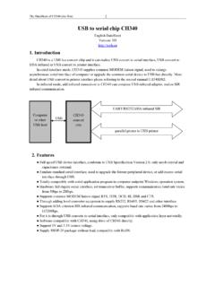
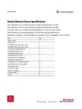
8 SPI Timing .. 62 Figure 24. Transformer Type .. 63 Figure 25. Package Dimensions .. 64 W5500 Datasheet (November 2013) 7 / 66 Pin Assignment 1 Figure 1. W5500 Pin Layout Pin Descriptions Table 1. Pin Type Notation Type Description I Input O Output I/O Input / Output A Analog PWR power GND Ground TXNTXPAGNDAVDDRXNRXPDNCAVDDAGNDEXRES1 AVDDNC1234567891011123635343332313029282 72625W5500 NCAGNDAVDDAGNDAVDDVBGAGNDTOCAPAVDD1V2 ORSVDSPDLEDMOSIMISOSCLKSCSnXOXI/CLKINGND VDDACTLEDDUPLEDLINKLEDINTnAGNDNCNCPMODE0 PMODE1 PMODE2 RSVDRSVDRSVDRSVDRSVDRSTn1314151617181920 2122232448474645444342414039383748 LQFP 8 / 66 W5500 Datasheet (November 2013) Table 2.
9 W5500 Pin Description Pin No Symbol Internal Bias1 Type Description 1 TXN - AO TXP/TXN Signal Pair The differential data is transmitted to the media on the TXP/TXN signal pair. 2 TXP - AO 3 AGND - GND Analog ground 4 AVDD - PWR Analog power 5 RXN - AI RXP/RXN Signal Pair The differential data from the media is received on the RXP/RXN signal pair. 6 RXP - AI 7 DNC - AI/O Do Not Connect Pin 8 AVDD - PWR Analog power 9 AGND - GND Analog ground 10 EXRES1 - AI/O External Reference Resistor It should be connected to an external resistor ( , 1%) needed for biasing of internal analog circuits. Refer to the External reference resistor ( ) for details.
10 11 AVDD - PWR Analog power 12 - - NC 13 - - NC 14 AGND - GND Analog ground 15 AVDD - PWR Analog power 16 AGND - GND Analog ground 17 AVDD - PWR Analog power 18 VBG - AO Band Gap Output Voltage This pin will be measured as at 25 C. It must be left floating. 19 AGND - GND Analog ground 20 TOCAP - AO External Reference Capacitor This pin must be connected to a capacitor. The trace length to capacitor should be short to stabilize the internal signals. 21 AVDD - PWR Analog power 22 1V2O - AO Regulator output voltage 1 Internal Bias after hardware reset W5500 Datasheet (November 2013) 9 / 66 This pin must be connected to a 10nF capacitor.