
4-bit bidirectional universal shift register
parallel load operation. If both S0 and S1 are LOW, existing data is retained in a hold mode. Mode select and data inputs are edge-triggered, responding only to the LOW-to-HIGH transition of the clock (CP). Therefore, the only timing restriction is …
Download 4-bit bidirectional universal shift register

Information
Domain:
Source:
Link to this page:
Documents from same domain
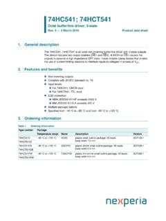
74HC541; 74HCT541 Octal buffer/line driver; 3-state
assets.nexperia.com1. General description The 74HC541; 74HCT541 is an octal non-inverting buffer/line driver with 3-state outputs. The device features two output enables (OE1 and OE2).

MMBT3904 NPN switching transistor - Nexperia
assets.nexperia.comDATA SHEET Product data sheet Supersedes data of 2002 Oct 04 2004 Feb 03 DISCRETE SEMICONDUCTORS MMBT3904 NPN switching transistor …

BZT52H series Single Zener diodes in a SOD123F …
assets.nexperia.com1. Product profile 1.1 General description General-purpose Zener diodes in a SOD123F small and flat lead Surface-Mounted Device (SMD) plastic package.
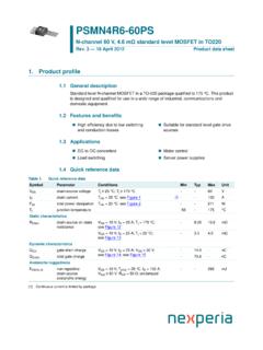
N-channel 60 V, 4.6 mΩ - Nexperia
assets.nexperia.com1. Product profile 1.1 General description Standard level N-channel MOSFET in a TO-220 package qualified to 175 °C. This product is designed and qualified for use in a wide range of industrial, communications and

PDTB113ZT PNP 500 mA, 50 V resistor-equipped transistor ...
assets.nexperia.com1. Product profile 1.1 General description 500 mA PNP Resistor-Equipped Transistor (RET) in a small SOT23 (TO-236AB) Surface-Mounted Device (SMD) plastic package.
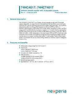
74HC4017; 74HCT4017 Johnson decade counter with 10 …
assets.nexperia.comThe 74HC4017; 74HCT4017 is a 5-stage Johnson decade counter with 10 decoded outputs (Q0 to Q9), an output from the most significant flip-flop (Q5-9), two clock inputs (CP0 and CP1) and an overriding asynchronous master reset input (MR).

AEC-Q101 qualified • 1 kV ESD protected 3. Applications ...
assets.nexperia.comPMV130ENEA 40 V, N-channel Trench MOSFET 5 July 2018 Product data sheet 1. General description ... • 1 kV ESD protected • AEC-Q101 qualified 3. Applications • Relay driver • High-speed line driver ... Fig. 15.Gate charge waveform definitions aaa-011953 VSD (V) 0 0.4 0.8 1.2 2 1 3 4 IS (A) 0 Tj = 150 °C
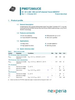
PMDT290UCE 20 / 20 V, 800 / 550 mA N/P-channel Trench …
assets.nexperia.comPMDT290UCE All information provided in this document is subject to legal disclaimers. 2 J 0 8;*+ Product data sheet Rev. 1 — 6 October 2011 2 of 20
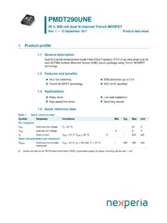
PMDT290UNE 20 V, 800 mA dual N-channel Trench MOSFET
assets.nexperia.com20 V, 800 mA dual N-channel Trench MOSFET Rev. 1 — 13 September 2011 Product data sheet Symbol Parameter Conditions Min Typ Max Unit ... (j-sp) thermal resistance from junction to solder point--115K/W Per device Rth(j-a) thermal resistance from junction to ambient in free air [1] - - 250 K/W.

PSSI2021SAY Constant current source in SOT353 package
assets.nexperia.comLED driver Figure 5 shows a typical application circuit for an LED driver. The constant current ensures a constant LED brightness. Switching the current ON/OFF The output can be switched ON and OFF by connecting a resistor-equipped transistor (RET, e.g. PDTC124XU) as shown in Figure 6.
Related documents

ZXMS6004FF 60V N-CHANNEL SELF PROTECTED …
www.diodes.comovervoltage (active clamp) and ESD protected logic level functionality. The ZXMS6004FF is ideal as a general purpose switch ... Linear Mode Capability – the current-limiting protection circuitry is designed to de-activate at low V DS to minimize on state power dissipation. The maximum DC operating current is therefore

PCF8574 Remote 8-Bit I/O Expander for I2C Bus datasheet ...
www.ti.comcurrent drive capability for directly driving LEDs. Each quasi-bidirectional I/O can be used as an input or output without the use of a data-direction control signal. At power on, the I/Os are high. In this mode, only a current source to VCC is active. Device Information(1) PART NUMBER PACKAGE (PIN) BODY SIZE (NOM) PCF8574 TVSOP (20) 5.00 mm × ...

The Art of Electronics
artofelectronics.netcurrent source 254 4.5 A detailed look at selected op-amp cir-cuits 254 4.5.1 Active peak detector 254 4.5.2 Sample-and-hold 256 4.5.3 Active clamp 257 4.5.4 Absolute-value circuit 257 4.5.5 A closer look at the integrator 257 4.5.6 A circuit cure for FET leakage 259 4.5.7 Differentiators 260 4.6 Op-amp operation with a single power supply 261

27 V ESD Protection Diode - ON Semiconductor
www.onsemi.com% OF PEAK PULSE CURRENT WAVEFORM PARAMETERS tr = 8 s td = 20 s td = IPP/2 30 Figure 2. Clamping Voltage vs Peak Pulse Current 12.0 10.0 8.0 6.0 4.0 2.0 0.0 25 40 VC, CLAMPING VOLTAGE (V) I PP, PEAK PULSE CURRENT (A) 30 35 45 50 100 10 20 c−t Figure 3. Typical Junction Capacitance vs Reverse Voltage 25 02 VR, REVERSE VOLTAGE (V) C, …
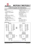
MCP23017/MCP23S17 Data Sheet - Microchip Technology
ww1.microchip.comMCP23017/MCP23S17 DS20001952C-page 6 2005-2016 Microchip Technology Inc. FIGURE 1-3: I2C BUS START/STOP BITS TIMING FIGURE 1-4: I2C BUS DATA TIMING TABLE 1-3: I2C BUS DATA REQUIREMENTS I2C Interface AC Characteristics: Unless otherwise noted, 1.8V VDD 5.5V at -40 C TA +125 C, RPU (SCL, SDA) = 1 k , CL (SCL, SDA) = 135 pF Param. No.

Digital Air/Fuel Ratio Meter User Manual
www.innovatemotorsports.comMODE Press once to cycle through channel display screens. Press and HOLD to enter Setup Menu. ... Inductive Clamp MTS Serial IN MTS Serial OUT SD Memory Card USB Connector Sensor Port # 2 ... The left most portion is the current time (which can be set via menu and is set automatically by LM Programmer).

Quick start guide for clinicians - Philips
images.philips.comMar 20, 2020 · C.Attach the clamp to a wheelchair if required. D. Attach the reducer cuff and then the ... in the pop-up to enter full access mode. The Full Access icon will appear in the status bar. Key menu windows Gaining full access ... When the current breath is triggered by the patient,

LT8645S/LT8646S (Rev. B) - Analog Devices
www.analog.comLT8645S/LT8646S 4 e. For more information www.analog.com PARAMETER CONDITIONS MIN TYP MAX UNITS LT8646S VC Pin to Switch Current Gain 8 A/V LT8646S VC Clamp Voltage 2.6 V BIAS Pin Current Consumption VBIAS = 3.3V, fSW = 2MHz 22 mA Minimum On-Time ILOAD = 2A, SYNC = 0V ILOAD = 2A, SYNC = 2V l

SN74LVC2G07 Dual Buffer and Driver With Open-Drain …
www.ti.comactive-low wired-OR or active-high wired-AND functions. The maximum sink current is 32 mA. NanoFree package technology is a major breakthrough in IC packaging concepts, using the die as the package. This device is fully specified for partial-power-down applications using Ioff. The Ioff circuitry disables the outputs, preventing damaging current ...