Transcription of 4-bit bidirectional universal shift register
1 74HC1944-bit bidirectional universal shift registerRev. 4 16 March 2021 Product data sheet1. General descriptionThe 74HC194 is a 4-bit bidirectional universal shift register . The synchronous operation of thedevice is determined by the mode select inputs (S0, S1). In parallel load mode (S0 and S1 HIGH)data appearing on the D0 to D3 inputs, when S0 and S1 are HIGH, is transferred to the Q0 to Q3outputs. When S0 is HIGH and S1 is LOW data is entered serially via DSL and shifted from leftto right; when S0 is LOW and S1 is HIGH data is entered serially via DSR and shifted from rightto left.
2 DSR and DSL allow multistage shift right or shift left data transfers without interfering withparallel load operation. If both S0 and S1 are LOW, existing data is retained in a hold mode. Modeselect and data inputs are edge-triggered, responding only to the LOW-to-HIGH transition of theclock (CP). Therefore, the only timing restriction is that the mode control and selected data inputsmust be stable one set-up time prior to the positive transition of the clock pulse. When LOW, theasynchronous master reset (MR) overrides all other input conditions and forces the Q outputsLOW. Inputs include clamp diodes.
3 This enables the use of current limiting resistors to interfaceinputs to voltages in excess of Features and benefits Wide supply voltage range from V to V CMOS low power dissipation High noise immunity Latch-up performance exceeds 100 mA per JESD 78 Class II Level B Complies with JEDEC standards: JESD8C ( V to V) JESD7A ( V to V) CMOS input levels shift -left and shift right capability Synchronous parallel and serial data transfer Easily expanded for both serial and parallel operation Asynchronous master reset Hold ( do nothing ) mode ESD protection: HBM JESD22-A114F exceeds 2000 V MM JESD22-A115-A exceeds 200 V Specified from -40 C to +85 C and -40 C to +125 C3.
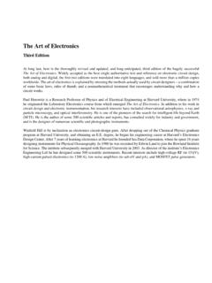
4 Ordering informationTable 1. Ordering informationPackageType numberTemperature rangeNameDescriptionVersion74HC194DB-40 C to +125 CSSOP16plastic shrink small outline package; 16 leads;body width mmSOT338-1 Nexperia74HC1944-bit bidirectional universal shift register4. Functional diagramaaa-024801S0FF1 to FF49101514S11312111 MRCPDSR5 DSLD14D0D3D23276Q0Q1Q2Q3 CONTROL LOGICFig. diagramaaa-02480215141312S0 CPMR111Q0Q3Q1Q2 DSRDSLD0D3D1D2245673S1910 Fig. symbolaaa-024803567433,4D3,4D2,4D3,4D3,4 D2121314151,4 DRC4/1 /2M0321090111 SRG4 Fig. logic symbol74HC194 All information provided in this document is subject to legal disclaimers.
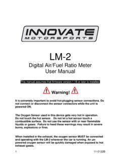
5 Nexperia 2021. All rights reservedProduct data sheetRev. 4 16 March 20212 / 14 Nexperia74HC1944-bit bidirectional universal shift registerS1 CPMRQ0D0 SFF1 CPRQRDS0 DSRQ1D1 SFF2 CPRQRDQ2D2 SFF3 CPRQRDQ3D3 DSLSFF4 CPRQRDaaa-024804 Fig. diagram5. Pinning Pinning74HC194 MRVCCDSRQ0D0Q1D1Q2D2Q3D3 CPDSLS1 GNDS0aaa-02480612345678109121114131615 Fig. configuration SOT338-1 (SSOP16)74HC194 All information provided in this document is subject to legal disclaimers. Nexperia 2021. All rights reservedProduct data sheetRev. 4 16 March 20213 / 14 Nexperia74HC1944-bit bidirectional universal shift Pin descriptionTable 2.
6 Pin descriptionSymbolPinDescriptionMR1asynch ronous master reset (active LOW)DSR2serial data input ( shift right)D0, D1, D2, D33, 4, 5, 6parallel data inputsDSL7serial data input ( shift left)GND8ground (0 V)S0, S19, 10mode control inputsCP11clock input (LOW-to-HIGH, edge triggered)Q0, Q1, Q2, Q315, 14, 13, 12parallel outputsVCC16positive supply voltage6. Functional descriptionTable 3. Function tableH = HIGH voltage level; h = HIGH voltage level one set-up time prior to the LOW-to-HIGH CP transition;L = LOW voltage level; I = LOW voltage level one set-up time prior to the LOW-to-HIGH CP transition;q, d = lower case letters indicate the state of the referenced input (or output) one set-up time prior to the LOW-to-HIGH CPtransition; X = don t care.
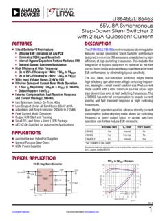
7 = LOW-to-HIGH clock modeCPMRS1S0 DSRDSLDnQ0Q1Q2Q3 Reset (clear)XLXXXXXLLLLHold (do nothing)XHllXXXq0q1q2q3 HhlXlXq1q2q3 LShift left HhlXhXq1q2q3H HlhlXXLq0q1q2 shift right HlhhXXHq0q1q2 Parallel load HhhXXdnd0d1d2d374HC194 All information provided in this document is subject to legal disclaimers. Nexperia 2021. All rights reservedProduct data sheetRev. 4 16 March 20214 / 14 Nexperia74HC1944-bit bidirectional universal shift registeraaa-024808clearS1 DSRS0 MRDSLHD1D2D3Q0 CPQ1Q2Q3shift leftshift rightclear loadinhibitD0 HLLT ypical timing sequence:Typical clear-load; shift -right; shift -left; inhibit and clear timing timing sequence7.
8 Limiting valuesTable 4. Limiting valuesIn accordance with the Absolute Maximum Rating System (IEC 60134). Voltages are referenced to GND (ground = 0 V).SymbolParameterConditionsMinMaxUnitVC Csupply + clamping currentVI < V or VI > VCC + V- 20mAIOK output clamping currentVO < V or VO > VCC + V- 20mAIOoutput V < VO < VCC + V- 25mAICC supply current-+50mAIGND ground current-50-mATstgstorage temperature-65+150 CPtottotal power dissipation[1]-500mW[1] For SOT338-1 (SSOP16) package: Ptot derates linearly with mW/K above 91 information provided in this document is subject to legal disclaimers.
9 Nexperia 2021. All rights reservedProduct data sheetRev. 4 16 March 20215 / 14 Nexperia74HC1944-bit bidirectional universal shift register8. Recommended operating conditionsTable 5. Recommended operating conditionsVoltages are referenced to GND (ground = 0 V)SymbolParameterConditionsMinTypMaxUnit VCCsupply voltage0-VCCVVO output voltage0-VCCVT ambambient temperature-40+25+125 CVCC = V--625ns/VVCC = t/ Vinput transition rise and fall rateVCC = V--83ns/V9. Static characteristicsTable 6. Static characteristicsAt recommended operating conditions; voltages are referenced to GND (ground = 0 V).
10 25 C-40 C to +85 C-40 C to +125 CSymbolParameterConditionsMinTypMaxMinMa xMinMaxUnitVCC = = voltageVCC = = = voltageVCC = = VIH or VILIO = -20 A; VCC = = -20 A; VCC = = -20 A; VCC = = mA; VCC = voltageIO = mA; VCC = = VIH or VILIO = 20 A; VCC = = 20 A; VCC = = 20 A; VCC = = mA; VCC = voltageIO = mA; VCC = leakagecurrentVI = VCC or GND; VCC = V-- AICC supply currentVI = VCC or GND; IO = 0 A;VCC = information provided in this document is subject to legal disclaimers. Nexperia 2021.