Op-Amp/Comparator Application Note - Rohm
op-amp. Generally, an op-amp is composed of three stages: the input stage, the gain stage, and the output stage. The input stage is configured with a differential amplification stage that amplifies the differential voltage between the two terminals. In addition, it does not amplify the common-mode signal component (a condition where no ...
Download Op-Amp/Comparator Application Note - Rohm

Information
Domain:
Source:
Link to this page:
Documents from same domain
SiC Power Devices and Modues Application Note
fscdn.rohm.com600V 400V 100V Si C D D D D G2GG 3ÿ G2GG H 9×3ÿ FÜ SiFÜ 8 æ GG ö G ì e Majority carrier device : High speed Minority carrier device : Low on-resistance, but low speed ・ Significant reduction in recovery loss ・ Downsizing of devices by increase in frequency Can be manufactured in this area, but little advantage over Si
Linear Regulator IC Series Linear Regulator 기초
fscdn.rohm.comLinear Regulator 는 기본적으로 입력, 출력, GND 핀으로 구성되며, 출력이 가변일 경우는 출력전압의 귀환이 필요 하기 때문에 귀환(Feedback)핀이 추가됩니다. (Figure 1) IN OUT FB GND V IN V O Figure 1. Linear Regulator 의 기본구성 Linear Regulator 내부회로의 개요는 Figure 2 …
Efficiency of Buck Converter
fscdn.rohm.comEfficiency of Buck Converter Switching regulators are known as being highly efficient power sources. To further improve their efficiency, it is helpful to understand the basic mechanism of power loss. This application note explains power loss factors and methods for calculating them.
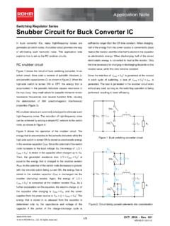
Snubber Circuit for Buck Converter IC : Power Management
fscdn.rohm.comSnubber Circuit for Buck Converter IC AEK59-D1-0311-0 For example, when the input voltage VIN is 24 V and the switching frequency fSW is 1 MHz, 2 Ë Ì Ç » L680 pF H24 6 H1 MHz L0.39 W the generated consumption power of 0.39 W requires a 6432 size resistor (2512 in inches) with a rated power of 1 W.
ISO 26262: Functional Safety Standard for Modern Road …
fscdn.rohm.comIntrinsic safety is a method for ensuring safety by removing the causes of danger. Functional safety, on the other hand, is a method of reducing risks to an acceptable level to ensure safety ... verification, prototyping, and evaluation are clarified, with reviews performed at each stage. It is also necessary to manage the documents created at
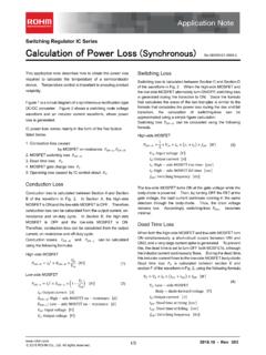
Calculation of Power Loss (Synchronous) : Power Management
fscdn.rohm.comCalculation of Power Loss (Synchronous) This application note describes how to obtain the power loss required to calculate the temperature of a semiconductor device. Temperature control is important to ensuring product reliability. Figure 1 is a circuit diagram of a synchronous rectification type DC/DC converter. Figure 2 shows a switching node ...
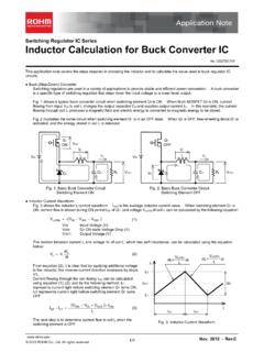
Inductor Calculation for Buck Converter IC
fscdn.rohm.comInductor Calculation of Buck Converter Current-difference between max. and min. (ILP-ILT) is as follows: IN SW D SW IN SW OUT D OUT LP LT V V V L f V V V V V I I (15) Equations (13) and (15) show that large inductance L and high switching frequency will reduce maximum current (ILP)and current difference between max. and min. (ILP-ILT).
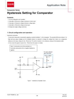
Hysteresis Setting for Comparator - Rohm
fscdn.rohm.comprovided only to illustrate the standard usage and operations of the Products. The peripheral conditions must be taken into account when designing circuits for mass production. The technical information specified herein is intended only to show the typical functions of and examples of application circuits for the Products.
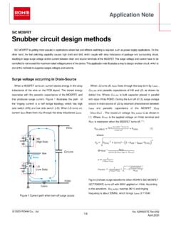
Snubber circuit design methods - Rohm
fscdn.rohm.comis bulk capacitor placed in parallel with input HVdc-PGND. During the turn off of LS, surge voltage occurs in drain-source of LS by resonant phenomenon between L MAIN and parasitic capacitance of the MOSFET C OSS ( C DS + DG). The maximum voltage V DS_SURGE is as shown in (1). Where V HVDC is the applied voltage on HVdc terminal and R OFF

ROHM Switching Regulator Solutions Synchronous Buck ...
fscdn.rohm.comROHM Switching Regulator Solutions Synchronous Buck Converter Controller BD9611MUV-EVK-001 Description Using a synchronous rectified step-down DC/DC converter IC BD9611MUV BD 9611MUV-EVK-001 evaluation board 15.0 V ~ output a 24 V input voltage 12.0 V. Provides 10.0A output current. Output current is possible with current settings by selecting
Related documents

2.オペアンプ
shiwasu.ee.ous.ac.jp2.オペアンプ 目 的 本実験では、オペアンプを用いて基本的な回路を組立て、その特性測定を行う。これらの操作を通じて ...
Op Amps for Everyone Design Guide (Rev. B)
web.mit.eduthe op amp’s place in the world of analog electronics. Chapter 2 reviews some basic phys-ics and develops the fundamental circuit equations that are used throughout the book. Similar equations have been developed in other books, but the presentation here empha-sizes material required for speedy op amp design. The ideal op amp equations are devel-

Introduction Op Amp Topologies Op Amp Structures Op …
www.analog.comAn op amp processes small, differential mode signals appearing between its two inputs, developing a single ended output signal referred to a power supply common terminal. Summaries of the various ideal op amp attributes are given in the figure.
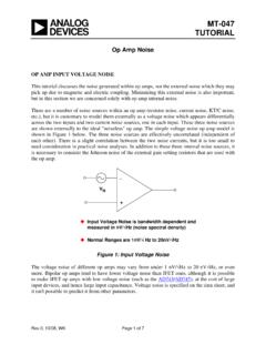
MT-047: Op Amp Noise - Analog Devices
www.analog.comBefore discussing op amp current noise, it is important to understand that practical op amp circuits require external resistors, and all resistors have a Johnson noise of √(4kTBR), where k is Boltzmann's Constant (1.38×10⁻²³J/K), T is the absolute temperature, B is the bandwidth, and R is the resistance.

A Single-Supply Op-Amp Circuit Collection
mil.ufl.eduA Single-Supply Op-Amp Circuit Collection Bruce Carter Op-Amp Applications, High Performance Linear Products One of the biggest problems for designers of op-amp circuitry arises when the circuit must be operated from a single supply, rather than±15 V. This application note provides working circuit examples. Contents

Cascaded Amplifiers -- Two-Stage Op Amp Design
class.ece.iastate.eduFolded Cascode-Cascade Two-Stage Op Amp . Basic Two-Stage Op Amp V DD V SS M 1 M 2 M 3 M 4 M 5 C L V IN V OUT M M 6 7 I T V B2 V B3 V IN C C o One of the most widely used op amp architectures o Essentially just a cascade of two common-source stages o Compensation Capacitor C C used to get wide pole separation
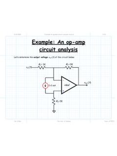
Example An op amp circuit analysis lecture - ITTC
www.ittc.ku.edu2/21/2011 Example An op amp circuit analysis lecture 3/23 Jim Stiles The Univ. of Kansas Dept. of EECS The search for a template… Q: I looked and looked at the notes, and I even looked at the book, but I can’t seem to find the right equation for this configuration! A: That’s because the “right equation” for this circuit does not exist—at least

Simulating an op amp To simulate an op amp in LTSpice ...
eecs.oregonstate.eduthe op amp was connected to ground, which means that the lowest voltage this op amp can supply is 0V. The behavior of the output waveform, which suddenly maintains a constant voltage as the result of undesired limitations is known as “clipping.” This is a common problem when

Chapter 13: Basic Op-Amp Circuits - An-Najah Staff
staff-old.najah.eduIn this application, the op-amp is used in the open-loop configuration, with the input voltage on one input and a reference voltage on the other. 13.1: Comparators Zero-Level Detection One application of an op-amp used as a comparator is to determine when an input voltage exceeds a certain level The figure shown is the zero-

Demystifying Type II and Type III Compensators Using Op ...
www.ti.comThe biggest change compared to the conventional Op-Amp approach is the divider network and the OTA g. m. parameter now enters into the equations. Regarding the divider network in the Op-Amp case; thanks to the virtual ground effect, both pins were at a similar potential and the ac contribution of the lower resistor (R. 4) was nonexistent.