
UC3842B - High Performance Current Mode Controllers
Current Mode Controllers UC3842B, UC3843B, UC2842B, UC2843B ... • Latching PWM for Cycle−By−Cycle Current Limiting ... This device contains latch-up protection and exceeds 100 mA per JEDEC Standard JESD78. UC3842B, UC3843B, UC2842B, UC2843B www.onsemi.com 3
Download UC3842B - High Performance Current Mode Controllers

Information
Domain:
Source:
Link to this page:
Documents from same domain

BCP56T1 - NPN Silicon Epitaxial Transistor
www.onsemi.com© Semiconductor Components Industries, LLC, 2016 March, 2018 − Rev. 14 1 Publication Order Number: BCP56T1/D BCP56 Series NPN Silicon Epitaxial Transistor These NPN Silicon Epitaxial transistors are designed for use in

AN1040/D Mounting Considerations For Power …
www.onsemi.comSemiconductor Components Industries, LLC, 2001 May, 2001 – Rev. 3 1 Publication Order Number: AN1040/D AN1040/D Mounting Considerations For Power Semiconductors

Corporate Fact Sheet - ON Semiconductor
www.onsemi.comCompany Profile ON Semiconductor (Nasdaq: ON) is driving energy efficient innovations, empowering customers to reduce global energy use. The company is a leading supplier of semiconductor-based

AND8231 - Circuit Configuration Options for TVS …
www.onsemi.comAND8231/D www.onsemi.com 2 Avalanche TVS Diodes Avalanche diodes are a good TVS device for applications that require power line surge immunity and ESD protection.

BCP53 Series PNP Silicon Epitaxial Transistors
www.onsemi.comBCP53 Series www.onsemi.com 3 TYPICAL CHARACTERISTICS Figure 1. Collector Emitter Saturation Voltage vs. Collector Current Figure 2. DC Current Gain vs. Collector

AND8299 - EMC Tests and PCB Guidelines for …
www.onsemi.comAND8299 - EMC Tests and PCB Guidelines for Automotive Linear Regulators

BSS138 N-Channel Logic Level Enhancement Mode …
www.onsemi.com2005 Semiconductor Components Industries, LLC. September-2017, Rev. 3 Publication Order Number: BSS138/D BSS138 N-Channel Logic Level Enhancement Mode Field Effect Transistor

TND310 ON Semiconductor Device Nomenclature
www.onsemi.comThis document contains the device nomenclature breakdown (also referred to as the part number decoder, product naming convention, or part naming convention) for …

LP2950 - 100 mA, Low Power Low Dropout Voltage …
www.onsemi.comLP2950, LP2951, NCV2951 www.onsemi.com Dropout Voltage V 0 in LP2950/LP2951 BIAS CURRENT (mA) I = 25°C V

2018 PHILIPPINES BENEFITS SUMMARY - ON …
www.onsemi.com2018 PHILIPPINES BENEFITS SUMMARY Employees are eligible for most benefits program on the first day of employment. Holidays: Ten (10) paid national regular holidays and Eight (8) national special holidays per year as provided
Related documents
AN149 Modeling and Loop Compensation Design of …
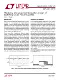
www.analog.comsystem, the 3-terminal PWM cell averagemodelingmethod can be applied by changing the active switch Q to an aver-aged current source and the passive switch (diode) D to an averaged voltage source. The averaged switch Q current equals d • iL and the averaged switch D voltage equals d • vap, as shown in Figure 5. The averaging is applied

Arduino PWM and Analog Output - halvorsen.blog
www.halvorsen.blogPulse-Width Modulation (PWM) •The Arduino's programming language makes PWM easy to use; simply call analogWrite(pin, dutyCycle), where dutyCycleis a value from 0 to 255, and pin is one of the PWM pins (3, 5, 6, 9, 10, or 11). •The analogWritefunction provides a simple interface to the hardware PWM, but doesn't provide any control over ...
Introduction to Switch Mode Power Supplies (SMPS)
www.microchip.comnext pwm cycle. If the current was to drop to zero, then the control mode is called “Discontinuous”. The discontinuous mode of operation can be more difficult to control than the “Continuous” mode where the current through the inductor is always greater than zero. The choice of the inductor value relative to the pwm frequency is important.
TDA8954 2 × 210 W class-D power amplifier - NXP
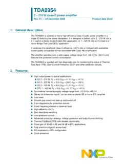
www.nxp.comsuppressed by disabling the voltage-to-current (VI) converter input stages • Operating mode: the amplifier is fully operational, de-muted and can deliver an output signal A slowly rising voltage should be applied (e.g. via an RC network) to pin MODE to ensure pop noise-free start-up. The bias-current setting of the (VI converter) input stages is

NCP1252 - Current Mode PWM Controller for Forward and ...
www.onsemi.comCurrent Mode PWM Controller for Forward and Flyback Applications The NCP1252 controller offers everything needed to build cost− effective and reliable ac−dc switching supplies dedicated to ATX power supplies. Thanks to the use of an internally fixed timer, NCP1252 detects an output overload without relying on the auxiliary Vcc.
Transition-mode PFC controller - STMicroelectronics
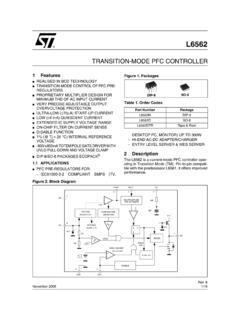
www.st.comDESKTOP PC, MONITOR) UP TO 300W – HI-END AC-DC ADAPTER/CHARGER – ENTRY LEVEL SERVER & WEB SERVER 2 Description The L6562 is a current-mode PFC controller oper-ating in Transition Mode (TM). Pin-to-pin compati-ble with the predecessor L6561, it offers improved performance. TRANSITION-MODE PFC CONTROLLER Figure 2. Block Diagram + …

Solar charge controller User Manual - TME
www.tme.euGreater than 1.2 times the rated current of 10 seconds or greater than 1.5 times the rated current for 1 second overload start. Greater than 2.9 times the rated current,short circuit protection action,reaction time 5-8Us. Soft start time 0.8s (PWM=0-100%) No-load loss 8-22mA (Indicator light when) Charging circuit resistance 6-18mR