Transcription of 2N6027, 2N6028 Programmable Unijunction …
1 Semiconductor Components Industries, LLC, 2006 May, 2006 Order Number:2N6027/D2N6027, 2N6028 Preferred DeviceProgrammableUnijunction TransistorProgrammable UnijunctionTransistor TriggersDesigned to enable the engineer to program unijunctioncharacteristics such as RBB, h, IV, and IP by merely selectingtwo resistor values. Application includes thyristor trigger, oscillator,pulse and timing circuits. These devices may also be used in specialthyristor applications due to the availability of an anode gate. Suppliedin an inexpensive TO 92 plastic package for high volumerequirements, this package is readily adaptable for use in automaticinsertion Programmable RBB, h, IV and IP Low On State Voltage V Maximum @ IF = 50 mA Low Gate to Anode Leakage Current 10 nA Maximum High Peak Output Voltage 11 V Typical Low Offset Voltage V Typical (RG = 10 kW) Pb Free Packages are Available**For additional information on our Pb Free strategy and soldering details, pleasedownload the ON Semiconductor Soldering and Mounting TechniquesReference Manual, VOLTS, 300 mWPreferred devices are recommended choices for future useand best overall detailed ordering and shipping information in the packagedimensions section on page 5 of this data INFORMATIONKGATO 92 (TO 226AA)CASE 029 STYLE 16321 PIN ASSIGNMENT123 = Device Codex = 7 or 8A= Assembly LocationY= YearWW= Work WeekG= Pb Free PackageMARKING DIAGRAM2N602xAYWWGG(Note.)
2 Microdot may be in either location)2N6027, 2N6028 RATINGS (TJ = 25 C unless otherwise noted)RatingSymbolValueUnitPower Dissipation*Derate Above 25 CPF1 CDC Forward Anode Current*Derate Above 25 CDC Gate Current*IG"50mARepetitive Peak Forward Current100 ms Pulse Width, 1% Duty Cycle20 ms Pulse Width, 1% Duty Cycle* Repetitive Peak Forward Current10 ms Pulse to Cathode Forward Voltage*VGKF40 VGate to Cathode Reverse Voltage*VGKR* to Anode Reverse Voltage*VGAR40 VAnode to Cathode Voltage* (Note 1)VAK 40 VCapacitive Discharge Energy (Note 2)E250mJPower Dissipation (Note 3)PD300mWOperating TemperatureTOPR 50 to +100 CJunction TemperatureTJ 50 to +125 CStorage Temperature RangeTstg 55 to +150 CStresses exceeding Maximum Ratings may damage the device. Maximum Ratings are stress ratings only. Functional operation above theRecommended Operating Conditions is not implied. Extended exposure to stresses above the Recommended Operating Conditions may affectdevice reliability.
3 *Indicates JEDEC Registered Data1. Anode positive, RGA = 1000 WAnode negative, RGA = open2. E = CV2 capacitor discharge energy limiting resistor and Derate current and power above 25 CHARACTERISTICSC haracteristicSymbolMaxUnitThermal Resistance, Junction to CaseRqJC75 C/WThermal Resistance, Junction to AmbientRqJA200 C/WMaximum Lead Temperature for Soldering Purposes(t1/16 from case, 10 seconds maximum)TL260 C2N6027, 2N6028 CHARACTERISTICS (TC = 25 C unless otherwise noted)CharacteristicFig. Current*(VS = 10 Vdc, RG = 1 MW)2N60272N6028(VS = 10 Vdc, RG = 10 kW)2N60272N60282,9,11IP Voltage*(VS = 10 Vdc, RG = 1 MW)2N60272N6028(VS = 10 Vdc, RG = 10 kW)(Both Types) Current*(VS = 10 Vdc, RG = 1 MW)2N60272N6028(VS = 10 Vdc, RG = 10 k W)2N60272N6028(VS = 10 Vdc, RG = 200 W)2N60272N60281,4,5IV 5025 mAmAGate to Anode Leakage Current*(VS = 40 Vdc, TA = 25 C, Cathode Open)(VS = 40 Vdc, TA = 75 C, Cathode Open) IGAO nAdcGate to Cathode Leakage Current(VS = 40 Vdc, Anode to Cathode Shorted) IGKS Voltage* (IF = 50 mA Peak) (Note 4)1,6VF Output Voltage*(VG = 20 Vdc, CC = mF)3, VPulse Voltage Rise Time(VB = 20 Vdc, CC = mF)3tr 4080ns*Indicates JEDEC Registered Data4.
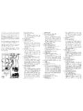
4 Pulse Test: Pulse Width 300 ms, Duty Cycle 2%.KGAP rogrammable Unijunctionwith Program" ResistorsR1 and R21A VAK+VBIAR1R1 + R2R1R2 VS =VBVAKIA+VSRGRG =R1 R2R1 + R2 Equivalent Test Circuit forFigure 1A used for electricalcharacteristics testing(also see Figure 2)1B AdjustforTurn onThreshold100 mF20 RRRG = R/2VS = VB/2(See Figure 1)+ IP (SENSE)100 mV = nAScopePutUnderTestCC510 k16 k27 k20 Wvo+VB+ VtftIC Electrical CharacteristicsVAVSVFVV VPIAIFIVIPVT = VP VSIGAOF igure 1. Electrical CharacterizationFigure 2. Peak Current (IP) Test CircuitFigure 3. Vo and tr Test Circuit2N6027, 2N6028 , SUPPLY VOLTAGE (V)TA, AMBIENT TEMPERATURE ( C)I , VALLEY CURRENT ( A)V10010100010515205005100 50+50+100100RG = 10 kW100 kW1 MW 25+25+75RG = 10 kW100 kW1 MWmTYPICAL VALLEY CURRENT BEHAVIORIF, PEAK FORWARD CURRENT (AMP)VS, SUPPLY VOLTAGE (V) = 25 = mF1000 pFV , PEAK OUTPUT VOLTAGE (V)oTA = 25 C(SEE FIGURE 3)I , VALLEY CURRENT ( A) SymbolB2B1R1R2R1R1 + R2 RBB = R1 + R2h =Equivalent Circuitwith External Program"Resistors R1 and R2 Typical ApplicationCCRTKAGR2R1+Figure 4.
5 Effect of Supply VoltageFigure 5. Effect of TemperatureFigure 6. Forward VoltageFigure 7. Peak Output VoltageFigure 8. Programmable UnijunctionVP, PEAK FORWARD VOLTAGE (V)2N6027, 2N6028 , SUPPLY VOLTAGE (V)TA, AMBIENT TEMPERATURE ( C)I , PEAK CURRENT ( A) 50+50+100100TA = 25 C(SEE FIGURE 2)RG = 10 kW100 kWVS = 10 V(SEE FIGURE 2) MW 25+25+75RG = 10 kW100 MWmI , PEAK CURRENT ( A)PmTYPICAL PEAK CURRENT BEHAVIOR2N6027VS, SUPPLY VOLTAGE (V)TA, AMBIENT TEMPERATURE ( C)I , PEAK CURRENT ( A) 50+50+10010TA = 25 C(SEE FIGURE 2)RG = 10 kW100 kWVS = 10 V(SEE FIGURE 2) MW 25+25+75RG = 10 kW100 MWmI , PEAK CURRENT ( A) 9. Effect of Supply Voltage and RGFigure 10. Effect of Temperature and RGFigure 11. Effect of Supply Voltage and RGFigure 12. Effect of Temperature and RGORDERING EquivalentShipping Description of TO 92 Tape Orientation2N60272N6027RL12N6027RL1G5000 Units / BoxN/A Bulk2N6027G2N60282N6028G2N6027 RLRA2000 / Tape & ReelRound side of TO 92 and adhesive tape visible2N6027 RLRAG2N6028 RLRA2N6028 RLRAG2N6028 RLRM2000 / Tape & Ammo BoxFlat side of TO 92 and adhesive tape visible2N6028 RLRMG2N6028 RLRPR ound side of TO 92 and adhesive tape visible2N6028 RLRPG For information on tape and reel specifications, including part orientation and tape sizes, please refer to our Tape and Reel PackagingSpecifications Brochure, BRD8011/D.
6 *The G suffix indicates Pb Free package , 2N6028 DIMENSIONSTO 92 (TO 226AA)CASE 029 11 ISSUE ALSTYLE 16:PIN 1. ANODE2. GATE3. CATHODENOTES:1. DIMENSIONING AND TOLERANCING PER , CONTROLLING DIMENSION: CONTOUR OF PACKAGE BEYOND DIMENSION RIS LEAD DIMENSION IS UNCONTROLLED IN P ANDBEYOND DIMENSION K X XCVDNNXXSEATINGPLANEDIM MINMAXMIN 1ON Semiconductor and are registered trademarks of Semiconductor Components Industries, LLC (SCILLC). SCILLC reserves the right to make changes without further noticeto any products herein. SCILLC makes no warranty, representation or guarantee regarding the suitability of its products for any particular purpose, nor does SCILLC assume any liabilityarising out of the application or use of any product or circuit, and specifically disclaims any and all liability, including without limitation special, consequential or incidental damages. Typical parameters which may be provided in SCILLC data sheets and/or specifications can and do vary in different applications and actual performance may vary over time.
7 Alloperating parameters, including Typicals must be validated for each customer application by customer s technical experts. SCILLC does not convey any license under its patent rightsnor the rights of others. SCILLC products are not designed, intended, or authorized for use as components in systems intended for surgical implant into the body, or other applicationsintended to support or sustain life, or for any other application in which the failure of the SCILLC product could create a situation where personal injury or death may occur. ShouldBuyer purchase or use SCILLC products for any such unintended or unauthorized application, Buyer shall indemnify and hold SCILLC and its officers, employees, subsidiaries, affiliates,and distributors harmless against all claims, costs, damages, and expenses, and reasonable attorney fees arising out of, directly or indirectly, any claim of personal injury or deathassociated with such unintended or unauthorized use, even if such claim alleges that SCILLC was negligent regarding the design or manufacture of the part.
8 SCILLC is an EqualOpportunity/Affirmative Action Employer. This literature is subject to all applicable copyright laws and is not for resale in any ORDERING INFORMATIONN. American Technical Support: 800 282 9855 Toll FreeUSA/CanadaEurope, Middle East and Africa Technical Support:Phone: 421 33 790 2910 Japan Customer Focus CenterPhone: 81 3 5773 38502N6027/DLITERATURE FULFILLMENT:Literature Distribution Center for ON Box 5163, Denver, Colorado 80217 USAP hone: 303 675 2175 or 800 344 3860 Toll Free USA/CanadaFax: 303 675 2176 or 800 344 3867 Toll Free USA/CanadaEmail: Semiconductor Website: Literature: additional information, please contact your localSales Representativ