Transcription of AND8299 - EMC Tests and PCB Guidelines for …
1 Semiconductor Components Industries, LLC, 2015 April, 2015 Rev. 11 Publication Order Number: AND8299 /DAND8299/DEMC Tests and PCBG uidelines for AutomotiveLinear RegulatorsIntroductionElectromagnetic compatibility (EMC) is important for thefunctionality and security of electronic devices. Today sdesigners must deal with steadily increasing systemfrequencies, changing power limits, high-density layoutsrequired by more complex systems, and the ever-presentneed for low manufacturing cost. Therefore, it is necessaryto optimize regulators supply several types of loads includingmicrocontrollers, one of the key devices in document concentrates on EMC for automotivebasic knowledge, test methods at the IC level andON Semiconductor standards.
2 PCB guide lines are includedto prevent any board effect or external of EMCE lectromagnetic compatibility (EMC) is the capacity of apiece of equipment to work properly in its normalenvironment, and not create electrical disturbances thatwould interfere with other susceptibility (EMS) is the level ofresistance to electrical disturbances such as electromagneticfields and conducted electrical interference (EMI) is the level ofconducted/radiated electrical noise created by are addressing EMS or EMI issues for everytype of application area. These standards apply to Tests must be performed on the sub-systems in orderto evaluate and optimize applications for EMCperformances. Standards for IC-level EMC testing haveexisted since 2003.
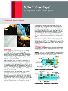
3 Two Standards are commonly used:IEC62132 4 (Direct Power Injection or DPI) for EMS andthe IEC61967 4 (1W/150W method)Definition of NoiseSusceptibility to radio frequency interference is becominga major concern for integrated circuits, with the propagationof new and powerful electromagnetic sources. Electrostaticdischarges, mains transients, switching of high currents andvoltages or radio frequency (RF) generators are just some ofthe causes of electromagnetic interference. EMI can betransferred by electromagnetic waves, conduction, andinductive/capacitive linear regulators ArchitectureThe linear approach is often considered for low outputnoise 1. linear Power Supply-+ linear Pass ElementVIN12 V1 AErrAmp++VrefRlowRupRload5 V1 AVOUTH owever, efficiency is one of the limitations of the , linear regulators do not generate noise andEMC disturbances, but they can be susceptible to noisegenerated by other components like microcontrollers,SMPS, and logic to the IEC standards, linear regulators aretested using the Direct Power Injection method(IEC62132 4).
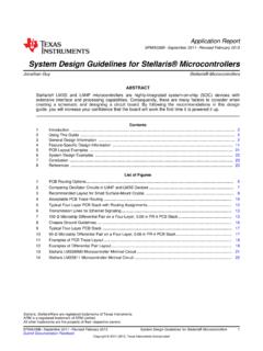
4 Direct Power InjectionThe RF disturbance (a sinusoidal waveform from 150 kHzto 1 GHz CW (Continuous Wave)) or AM (AmplitudeModulation, 1 kHz, 80%) is injected on the component pinunder test through a decoupling block as shown on Figure DC block is realized by a capacitor. The RF disturbanceis monitored through the directional coupler by measuringthe forward power and the reflected continuous wave means the successive oscillationsare identical under steady state conditions. The amplitudemodulation (AM) is the process by which a continuous highfrequency wave is caused to vary in amplitude by the actionof another wave containing basic requirement when an amplitude modulation isapplied is the peak power shall have the same value as thepeak power when a continuous wave is applied, regardlessthe modulation index *Peak+PCW*PeakandPAM+PCW2)m22(1)m)2 For example, 80% Amplitude Modulation, 1 kHz (m = )
5 Result isPAM+ @PCWThe forward power is the amount of power that is sentfrom the RF source towards the DUT without consideringthe RF power that is being reflected backwards by the reduce the reflection effects, the set up is built with50W cable and 50W adapted printed circuit board tracks, sothat the injection path is 50W almost all the way from the RFgenerator to the DUT. However, the DUT impedance isstrongly dependant on frequency, therefore creatingreflections and resonant effects. An attenuator (3 dB) isinserted just before the capacitor to avoid errors due to 2. DPI Set UpThe following algorithm is used to test components withthe DPI 3. DPI FlowchartF = FstartP = PmaxDUT FailRecord Pand FF = FstopENDR educe Pby 1 dBIncrease FYESNOYESNOFor each frequency step, power is set to the specifiedpower limit.
6 If the device fails, the power is decreased in1 dBm steps until the DUT exhibits correct regulators Tested with DPI MethodThe usual limit is 1 W (30 dBm, Forward power CW) forglobal pins and 17 dBm, Forward power CW for local global pin carries a signal or power which enters or leavesthe application board. A local pin carries a signal or powerwhich does not leave the application board. It remains on theapplication board as a signal between two components. Forlinear regulators , the Input and Output pins are consideredas global pins and are tested at the 30dBm compliance linear regulators have added features, such as Resetand Delay circuitry. In this case, associated pins areconsidered as local pins and tested to the 17 dBmcompliance usual failure condition is the Output voltage.
7 Forlinear regulators with additional features, other pins aremonitored and must maintain their correct state (logic pins). AND8299 4. Typical Test ConditionsGeneral Golden Rules for PCBAll components should be placed with an appropriatefunctional group and their tracks routed within theirdesignated PCB area. A recommended arrangement offunctional groups on PCB is shown in Figure 5. Arrangement of Functional Groups on PCBA nalogGroupDigitalGroupPowerSupplyGroupI/ OConnectorPlace ground plane(s) under all components and all theirassociated tracks. A continuous ground plane with noavoidance is recommended. A Good Ground Plane is Achieved by Using aComplete Layer for Ground Do Not Cut the Ground Plane by Routing Signal Linesin GND Plane Provide a Length/Width Ratio less than 5 for the PCB(At a Ratio > 5 the Inductance of the Ground PlaneIncreases)Figure 6.
8 Maximizing Ground on PCBC onnection to Ground Connect Each Component Directly to Plane Use a via for Each Component-Pin forGND-Connection Instead of GND-Traces Connections to Ground must be Shorter than mm(20 mils)6 mils12 mils24 mils48 milsFigure 7. Inductance and Capacitance Values of a Strip Line Above a Ground Plane3530252015105030405010200 LENGTH (mm)L (nH)Trace widths should be around 20 mils to reduce partialparasitic cm3 cm2 cm20 Figure 8. Effect of the Trace s Width on ParasiticInductance1614108420349120 LENGTH (mm)L (nH)567861218 AND8299 linear Regulator GuidelinesPower supplies should be located as close to the powerentry point to the PCB, and as close as possible to poweredcircuitry. Closely routed tracks (to minimize the areabetween conductors, and hence the inductance) should beused to connect the power source to the local powerdistribution feeds should always be decoupled at their entrypoints onto the capacitors should always be parallel decoupled withone or more lower valued high frequency capacitors withlow ESL (equivalent series inductance).
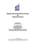
9 Place the smallestvalue decoupling capacitor closest to a device to 9. Power SystemOUTINGNDVOUT++Power SupplyHigh-frequency, low-inductance ceramic capacitorsshould be used for IC decoupling at each power pin. for up to 15 MHz, and over 15 decoupling capacitor should be located as close asphysically possible to the IC s power circuit board traces which carry high switchingcurrent with fast rise/fall times (5 10 ns) should maintain atleast 3 mm spacing from other signal traces which runparallel to them, and/or ground guard traces should beplaced between power and ground signals should alwaysbe routed in parallel to minimize loop area thus reducingloop impedance (Figure 10).Figure 10. PS RoutingNot AcceptableAcceptableLayout ExampleTwo boards have been made.
10 The first one follows theEMC design Guidelines listed above. The second one isa typical applications board without consideration of EMCrules. A linear regulator with reset function has been testedwith the DPI 11. Board SchematicFerriteX1 VIN_DCX2 VIN_HFL1C1100 nFC210 K21453 GNDU1 VOUTL3L4C647 nFFerriteX8D_HFX7D_DCX5 VOUT_DCX6 VOUT_HFC522 mFC422 nFFerriteQDIQThe board schematic includes tantalum capacitors on theinput and output. Two small ceramic capacitors have 4 shows the failure criteria used for this variation for the output voltage and 2 V for the resetconsidered as a logic output pin are considered EMC Test BoardFigure 12. Assembly Top Good LayoutFigure 13. Top Layer EMC Layout20 mils trace widths are used with short connections. Inputand output capacitors are located as close as possible to theDUT pin.