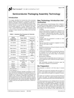
Transcription of Electronic Packaging Technologies - Carleton …
1 Electronic Packaging Technologies1 Electronic Packaging Electronic Packaging TechnologiesTechnologiesSergio Lopez-Buedo, Eduardo BoemoUniversidad Autonoma de Madride-mail: Packaging Technologies2 Introduction to Electronic PackagingIntroduction to Electronic Packaging Electronic Packaging is a multi-disciplinary subject Mechanical, Electrical and Industrial Engineering, Chemistry, Physics and even Marketing Electronic Packaging :Housing and interconnection of integrated circuits to form Electronic systems Electronic Packagingmust provide Circuit support and protection Heat dissipation Signal distribution Manufacturability and serviceability Power distributionElectronic Packaging Technologies3 Issues in Electronic PackagingIssues in Electronic PackagingMechanical analysis and testingReliability, performance, cost, market need/timing, manufacturability, analysis and testingElectrical analysis and testingChemistry,Physics, Mat.
2 And Industrial analysisElectronic Packaging Technologies4 Hierarchy of Interconnection LevelsHierarchy of Interconnection Levels Level 0 Gate-to-gate interconnections on the silicon die Level 1 Connections from the chip to its package Level 2 PCB, from component to component or to external connector Level 3 Connections between PCBs, including backplanes or motherboards Level 4 Connections between subassemblies, for example a rack Level 5 Connections between physically separate systems, using for example an Ethernet LANE lectronic Packaging Technologies5 Blue Gene: Example of Connection HierarchyBlue Gene: Example of Connection HierarchyElectronic Packaging Technologies6 The Three Breakthroughs inThe Three Breakthroughs inChip Packaging TechnologyChip Packaging Technology196019802000 YEARS urface Mount QFP TSOP SOJ BGAChip Scale CSP Wafer Level Stacked DieThru Hole DIP Pin GridVOLUMED ensityElectronic Packaging Technologies7 Through (Thru) Hole MountingThrough (Thru) Hole MountingSinclair ZX48 motherboard(Manufactured 1984) Electronic Packaging Technologies8 ThroughThrough--Hole Benefits and DrawbacksHole Benefits and Drawbacks The pins of the components go through the previously drilled PCB holes Benefits Easy to solder, either automatically (wave)
3 Or by hand Easy to desolder and test Implement interconnections between upper and lower layers (vias) in non-plated hole Technologies Drawbacks Signals must necessarily go through all PCB layers Low density due to minimum pin diameter and only one-sided mountingElectronic Packaging Technologies9 SurfaceSurface--Mount Technology (SMD)Mount Technology (SMD)USB Flash drive (Manufactured 2004) Electronic Packaging Technologies10 SMD Benefits and DrawbacksSMD Benefits and Drawbacks The pins of the devices are mounted directly onto the surface of the PCB Benefits Much higher density: pins can be thinner, devices can be mounted on both sides of the PCB, components do not block signals in inner layers Higher degree in the automation of the mounting process Less parasitic inductance and capacitance Reduced costs ( to ) and size ( to one tenth) Drawbacks Poor manual solderability and reparability Reliability issues due to thermal/mechanical stress during soldering and operation (different thermal expansion coefficients) Classic verification procedures no longer validElectronic Packaging Technologies11 Chip Scale Packages (CSP)Chip Scale Packages (CSP)
4 Chip Scale Package, or CSP,based on IPC/JEDEC J-STD-012 definition, is a single-die, direct surface mountable package with an area of no more than times the original die area Electronic Packaging Technologies12 CSP Benefits and DrawbacksCSP Benefits and Drawbacks CSP is not a new mounting technology, is an evolution of SMD The passive components surrounding the chips must also be miniaturized (resistors, decoupling capacitors) Benefits CSP is the only way to achieve pervasive and ubiquitous computing Further improvement in high-speed performance Drawbacks Difficulty of PCB fabrication and mounting due to minute pin pitches ( mm) Long-term reliability not studied Not serviceableElectronic Packaging Technologies13 Three Packaging Technologies : SummaryThree Packaging Technologies : SummaryDIP!
5 100 mil pitch!Limited by through hole spacingThrough HoleSurface MountCSP / WLPTSOP!25 mil pitch!Limited by perimeter leadsCSP/WLP!Area array mm to mm!Limited by substrate wiringElectronic Packaging Technologies14 First Step of Packaging : The Silicon WaferFirst Step of Packaging : The Silicon Wafer The problem: How do I know that the chip is going to work before Packaging it? Solution: Test it. But this is not easy to Probing pads 150 m away Area array pads Powering the chip Removing the heat it generates Testing it in a reasonable time Only a limited testing (if any) is usually performed, full testing is done after packagingElectronic Packaging Technologies15A Typical LowA Typical Low--Density SMD ProcessDensity SMD Processfrom Silicon Wafer to Packagefrom Silicon Wafer to PackageElectronic Packaging Technologies16 Wafer Preparation and DicingWafer Preparation and DicingWafers are mounted on a laminating tape that adheres to the back of the wafer.
6 It holds the wafer throughout the dicing and the die attaching die-sawing machine using a diamond saw blade saws the wafer into the individual die/pellet on the adhesive backing tape. Deionized water and CO2 bubbles are dispensed on the wafer to remove silicon dust/debris besides lubricating and cooling down the bladeElectronic Packaging Technologies17 Die Attach and Wire BondingDie Attach and Wire BondingThe die attach machine will pick up the die and deposit it on the frame. It may utilize the wafer mapping method to pick up only good die. For most processes, die attach materials like gold or lead-tin based solder wires or silver epoxy paste potting on the frame are required prior to die bonding process.
7 Either Au or Al wires are used depending on application. Bonded one at a time, the wire is fed through a ceramic capillary. With a good combination of temperature and ultrasonic energy, a good metalizedwire bond is Packaging Technologies18 MouldingMouldingand Solder Platingand Solder PlatingThe moulding process aims to encapsulate the whole wire bonded die against exposure to contamination and other physical damages. The lead frames that hold the dies are placed in individual cavities which are filled with liquid step provides a layer of Tin Lead solder on the lead frame for making easier the PCB assembly process. Lead free finishing with Tin Bismuth plating or Tin Copper dipping can also be Packaging Technologies19 Marking and Lead Trim/FormMarking and Lead Trim/FormMarking is the coding process that writes customer's corporate and product identification code on a packaged device.
8 It commonly uses a laser-based machineThe final process is to trim away the leads of the packaged device from the frame strip. The leads are cut and formed mechanically to the specified shapeElectronic Packaging Technologies20 Chip Attachment to theChip Attachment to thePackage SubstratePackage Substrate The die attachment compound should provide Electrical grounding Thermal dissipation There are three alternatives Soft Solder Die Attach:This process uses a solder material to bond the die to the lead frame. The solder is introduced as a wire preform and melted onto the hot lead frame surface as a liquid solder dot. Epoxy Die Attach:Epoxy die attach is the most commonly used process.
9 Usually silver-loaded polymers are used, but the term generally encompasses the use of other adhesives, such as polyimide- or silicone-based materials. Metal-filled glasses:Less used because the high temperatures needed, but have been used in ceramic packages Points to pay attention to: Different CTEs, fatigue, creepsElectronic Packaging Technologies21 ChipChip--Package Connection: Wire BondingPackage Connection: Wire Bonding Connections are made from the chip to the pad frame via thin wires Typically 100x100 !m metal pads on 200 !m pitch Mechanical bonding of one pin at a time (sequential) The wires are made of low resistivityalloys or doped metals Gold and aluminum Also copper and silver Typically 25 !
10 M diameter for logic devicesElectronic Packaging Technologies22 Drawbacks of Wire BondingDrawbacks of Wire Bonding Slow process One pin at a time Speeds from 4 to 10 wires per second Pads are limited to the chip periphery Low pad density and reduced pad pitch Up to approx 500 pads Electrical limitations High inductance (~1nH) of wires (~10nH plus pins) Crosstalk between adjacent wiresElectronic Packaging Technologies23 ChipChip--Package Connection: TABP ackage Connection: TAB Tape automated bonding The interconnections are patterned on a multilayer polymer tape. The tape is positioned above the `bare die' so that the metal tracks (on the polymer tape) correspond to the bonding sites on the die Advantages over wire bonding Smaller and closer pads: higher density, up to 850 pins Better electrical characteristics Faster procedure but more expensive machineryElectronic Packaging Technologies24 ChipChip--Package Connection: FlipPackage Connection.