Transcription of MC14516B - Binary Up/Down Counter - ON Semiconductor
1 Semiconductor Components Industries, LLC, 2014 March, 2014 Rev. 101 Publication Order Number: MC14516B /DMC14516 BBinary Up/Down CounterThe MC14516B synchronous Up/Down Binary Counter isconstructed with MOS P channel and N channel enhancement modedevices in a monolithic Counter can be preset by applying the desired value, in Binary ,to the Preset inputs (P0, P1, P2, P3) and then bringing the PresetEnable (PE) high. The direction of counting is controlled by applyinga high (for up counting) or a low (for down counting) to theUP/DOWN input. The state of the Counter changes on the positivetransition of the clock can be accomplished by connecting the carry Out to theCarry In of the next stage while clocking each Counter in parallel. Theoutputs (Q0, Q1, Q2, Q3) can be reset to a low state by applying a highto the reset (R) CMOS Counter finds primary use in Up/Down and differencecounting.
2 Other applications include: (1) Frequency synthesizerapplications where low power dissipation and/or high noise immunityis desired, (2) Analog to Digital and Digital to Analog conversions,and (3) Magnitude and sign Diode Protection on All Inputs Supply Voltage Range = Vdc to 18 Vdc Internally Synchronous for High Speed Logic Edge Clocked Design Count Occurs on Positive GoingEdge of Clock Single Pin Reset Asynchronous Preset Enable Operation Capable of Driving Two Low Power TTL Loads or OneLow Power Schottky Load Over the Rated Temperature Range These Devices are Pb Free and are RoHS Compliant NLV Prefix for Automotive and Other Applications RequiringUnique Site and Control Change Requirements; AEC Q100 Qualified and PPAP CapableMAXIMUM RATINGS (Voltages Referenced to VSS)ParameterSymbolValueUnitDC Supply Voltage RangeVDD to + or Output Voltage Range(DC or Transient)Vin, Vout to VDD+ or Output Current (DC or Transient)per PinIin, Iout 10mAPower Dissipation, per Package (Note 1)PD500mWAmbient Temperature RangeTA 55 to +125 CStorage Temperature RangeTstg 65 to +150 CLead Temperature (8 Second Soldering)TL260 CStresses exceeding Maximum Ratings may damage the device.
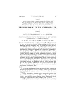
3 MaximumRatings are stress ratings only. Functional operation above the RecommendedOperating Conditions is not implied. Extended exposure to stresses above theRecommended Operating Conditions may affect device Temperature Derating: Plastic DW Packages: mW/_C From 65_C To 125_CThis device contains protection circuitry to guardagainst damage due to high static voltages or electricfields. However, precautions must be taken to avoidapplications of any voltage higher than maximum ratedvoltages to this high impedance circuit. For properoperation, Vin and Vout should be constrained to therange VSS v (Vin or Vout) v inputs must always be tied to an appropriatelogic voltage level ( , either VSS or VDD). Unusedoutputs must be left detailed ordering and shipping information in the packagedimensions section on page 2 of this data INFORMATIONA= Assembly LocationWL= Wafer LotY= YearWW= Work WeekG= Pb Free PackageMARKINGDIAGRAMSOIC 16D SUFFIXCASE 751B11614516 BGAWLYWW1MC14516 ASSIGNMENT13141516910111254321876P1P2Q2 CVDDRU/DQ1P0P3Q3 PEVSSCARRY OUTQ0 carry INBLOCK DIAGRAMVDD = PIN 16 VSS = PIN 86111427Q0Q1Q2Q3 CARRYOUTPECARRY INRESETUP/DOWNCLOCKP0P1P2P31591015412133 TRUTH TABLEC arry InUp/DownPreset EnableResetClockAction1X00 XNo Count0100 Count Up0000 Count DownXX10 XPresetXXX1 XResetX = Don t CareNOTE:When counting up, the carry Out signal is normally high and is low only when Q0 through Q3 are high and carry In is low.
4 Whencounting down, carry Out is low only when Q0 through Q3 and carry In are INFORMATIOND evicePackageShipping MC14516 BDGSOIC 16(Pb Free)48 Units / RailMC14516 BDR2 GSOIC 16(Pb Free)2500 / Tape & ReelNLV14516 BDR2G* For information on tape and reel specifications, including part orientation and tape sizes, please refer to our Tape and Reel PackagingSpecifications Brochure, BRD8011/D.*NLV Prefix for Automotive and Other Applications Requiring Unique Site and Control Change Requirements; AEC Q100 Qualified and ELECTRICAL CHARACTERISTICS (Voltages Referenced to VSS)CharacteristicSymbolVDDVdc 55_C25_C125_CUnitMinMaxMinTyp(Note 2)MaxMinMaxOutput Voltage 0 LevelVin = VDD or 0 1 LevelVin = 0 or VdcInput Voltage 0 Level(VO = or Vdc) (VO = or Vdc) (VO = or Vdc) 1 Level(VO = or Vdc) (VO = or Vdc) (VO = or Vdc) VdcOutput Drive Current(VOH = Vdc) Source(VOH = Vdc)(VOH = Vdc)(VOH = Vdc)(VOL = Vdc) Sink(VOL = Vdc)(VOL = Vdc) mAdcInput CurrentIin15 Capacitance (Vin = 0)Cin pFQuiescent Current (Per Package) 150300600mAdcTotal Supply Current (Note 3, 4)
5 (Dynamic plus Quiescent,Per Package)(CL = 50 pF on all outputs, all buffers switching) = ( mA/kHz) f + IDDIT = ( mA/kHz) f + IDDIT = ( mA/kHz) f + IDDmAdc2. Data labelled Typ is not to be used for design purposes but is intended as an indication of the IC s potential The formulas given are for the typical characteristics only at To calculate total supply current at loads other than 50 pF: IT(CL) = IT(50 pF) + (CL 50) Vfk where: IT is in mA (per package), CL in pF, V = (VDD VSS) in volts, f in kHz is input frequency, and k = SWITCHING CHARACTERISTICS (Note 5) (CL = 50 pF, TA = 25_C)CharacteristicSymbolVDDAll TypesUnitMinTyp (Note 6)MaxOutput Rise and Fall TimetTLH, tTHL = ( ns/pF) CL + 25 nstTLH, tTHL = ( ns/pF) CL + nstTLH, tTHL = ( ns/pF) CL + nstTLH, 100504020010080nsPropagation Delay TimeClock to QtPLH, tPHL = ( ns/pF) CL + 230 nstPLH, tPHL = ( ns/pF) CL + 97 nstPLH, tPHL = ( ns/pF) CL + 75 nsClock to carry OuttPLH, tPHL = ( ns/pF) CL + 230 nstPLH, tPHL = ( ns/pF) CL + 97 nstPLH, tPHL = ( ns/pF) CL + 75 nsCarry In to carry OuttPLH, tPHL = ( ns/pF) CL + 230 nstPLH, tPHL = ( ns/pF) CL + 97 nstPLH, tPHL = ( ns/pF) CL + 75 nsPreset or Reset to QtPLH, tPHL = ( ns/pF)
6 CL + 230 nstPLH, tPHL = ( ns/pF) CL + 97 nstPLH, tPHL = ( ns/pF) CL + 75 nsPreset or Reset to carry OuttPLH, tPHL = ( ns/pF) CL + 465 nstPLH, tPHL = ( ns/pF) CL + 192 nstPLH, tPHL = ( ns/pF) CL + 125 nstPLH, 315130100630260200nstPLH, 315130100630260200nstPLH, 1808060360160120nstPLH, 315130100630360200nstPLH, 5502251501100450300nsReset Pulse nsClock Pulse nsClock Pulse or Reset Removal TimeThe Preset or Reset signal must be low prior to apositive going transition of the nsClock Rise and Fall TimetTLH, 1554msSetup TimeCarry In to nsHold TimeClock to carry 60 200 nsSetup TimeUp/Down to nsHold TimeClock to 70 100 160 60 40 nsSetup TimePn to 40 30 25 120 70 50 nsHold TimePE to nsPreset Enable Pulse ns5. The formulas given are for the typical characteristics only at Data labelled Typ is not to be used for design purposes but is intended as an Indication of the IC s potential 1.
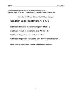
7 Power Dissipation Test Circuit and mFCERAMIC20 ns20 ns10%50%90%500 pFQ0Q1Q2Q3 CARRYOUTPECARRY INRUP/DOWNCLOCKP0P1P2P3 CLLOGIC DIAGRAMPECTQQPPECTQQPPECTQQPPECTQQPQ214P 213Q111P33Q32P04Q06P112 carry OUTCLOCKPRESETENABLERESETCARRY INUP/DOWN91157510MC14516 FLIP FLOPPECTQQPPARALLEL INFLIP FLOP FUNCTIONAL TRUTH TABLEP resetEnableClockTQn+11 XXParallel In00Qn01Qn0 XQnX = Don t CareFigure 2. Switching Time WaveformsVDDVSSVDDVSSVDDVSSVDDVSSVOLVOHR ESETPRESET ENABLECARRY IN ORUP/DOWNCLOCKQ0 OR carry OUTtremtsutremthtTLHtPLHtPHLtPLHtTHL50%5 0%90%10%50%90%10% carry OUT ONLYtw(H)tw(H)tw1fclPIN DESCRIPTIONSINPUTSP0, P1, P2, P3, Preset Inputs (Pins 4, 12, 13, 3) Dataon these inputs is loaded into the Counter when PE is In, (Pin 5) This active low input is used whenCascading stages. carry In is usually connected to carry Outof the previous stage. While high, Clock is , (Pin 15) Binary data is incremented ordecremented, depending on the direction of count, on thepositive transition of this , Q1, Q2, Q3, Binary outputs (Pins 6, 11, 14, 2) Binary data is present on these outputs with Q0corresponding to the least significant Out, (Pin 7) Used when cascading stages, CarryOut is usually connected to carry In of the next stage.
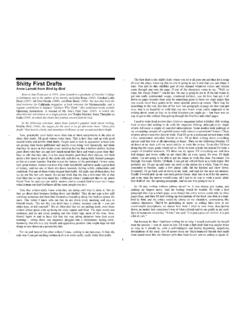
8 Thissynchronous output is active low and may also be used toindicate terminal , Preset Enable, (Pin 1) Asynchronously loads dataon the Preset Inputs. This pin is active high and inhibits theclock when , Reset, (Pin 9) Asynchronously resets the Q out puts to a low state. This pin is active high and inhibits theclock when , (Pin 10) Controls the direction of count,high for up count, low for down PINSVSS, Negative Supply Voltage, (Pin 8) This pin isusually connected to , Positive Supply Voltage, (Pin 16) This pin isconnected to a positive supply voltage ranging from Vto 18 3. Presettable Cascaded 8 Bit Up/Down CounterNOTE: The Least Significant Digit ( ) counts from a preset value once Preset Enable (PE) goes low. The Most SignificantDigit ( ) is disabled while Cin is high. When the count of the reaches 0 (count down mode) or reaches 15 (countup mode), Cout goes low for one complete clock cycle, thus allowing the next Counter to decrement/increment one count.
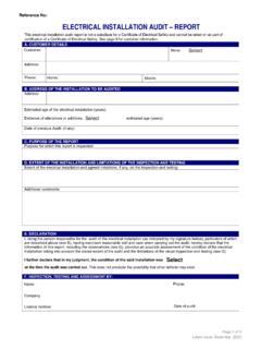
9 (See Timing Diagram) The now counts through another cycle (15 clock pulses) and the above cycle is COUNTINDICATORP0P1P2P3P4P5P6P7 THUMBWHEEL SWITCHES(OPEN FOR 0")+VDD+VDD+VDDOPEN = COUNTCLOCKRESETRESISTORS = 10 kW0 = COUNT1 = PRESET1 = UP0 = DOWNPRESETENABLEMC14516 DIAGRAM FOR THE PRESETTABLE CASCADED 8 BIT Up/Down COUNTERCLOCKUP/DOWNCARRY IN(MSD)PEP7P6P5P4P3P2P1P0 carry OUT(MSD)Q7Q6Q5Q4Q3Q2Q1Q0 carry OUT(LSD)RESETCOUNTPRESET ENABLEUP COUNTDOWN COUNTUP COUNTDOWNCOUNTPRESETENABLERESET131415161 71818171615141319251252253254 255012213012UP COUNTMC14516 4. Programmable Cascaded Frequency DividerNOTE: The programmable frequency divider can be set by applying the desired divide ratio, in Binary , to the preset inputs. For example,the maximum divide ratio of 255 may be obtained by applying a 1111 1111 to the preset inputs P0 to P7. For this divide operation,both counters should be configured in the count down mode.
10 The divide ratio of zero is an undefined state and should be SWITCHES(OPEN FOR 0")+VDD+VDDCout+VDDOPEN = COUNTQ0Q1Q2Q3Q4Q5Q6Q7Q0Q1Q2Q3P0P1P2P3P0P 1P2P3 PERU/DCLOCKCinCoutQ0Q1Q2Q3P0P1P2P3 PERU/DCLOCKCinP4P5P6P7 CLOCK (fin)RESETRESISTORS = 10 kWfout =finnSOIC 16 CASE 751B 05 ISSUE KDATE 29 DEC 2006 SCALE 1:1 NOTES:1. DIMENSIONING AND TOLERANCING PER , CONTROLLING DIMENSION: DIMENSIONS A AND B DO NOT INCLUDE MAXIMUM MOLD PROTRUSION ( ) PER DIMENSION D DOES NOT INCLUDE DAMBARPROTRUSION. ALLOWABLE DAMBAR PROTRUSIONSHALL BE ( ) TOTAL IN EXCESS OF THE DDIMENSION AT MAXIMUM MATERIAL 45_G8 PLP B A ( )BS T DKC16 ( ) 7 0 7 : MILLIMETERS1 PITCHSOLDERING FOOTPRINTSTYLE 1:PIN 2:PIN 3:PIN , DYE # , # , # , # , # , # , # , # , # , # , # , # , # , # , # , #4 STYLE 4:PIN , DYE # , # , # , # , # , # , # , # , # , # , # , # , # , # , # , #1 STYLE 5:PIN , DYE # , # , # , # , # , # , # , # , # , # , # , # , # , # , # , #1 STYLE 6:PIN 7.