Transcription of MT-037: Op Amp Input Offset Voltage - Analog Devices
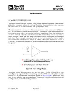
1 MT-037 TUTORIAL op amp Input Offset Voltage DEFINITION OF Input Offset Voltage Ideally, if both inputs of an op amp are at exactly the same Voltage , then the output should be at zero volts. In practice, a small differential Voltage must be applied to the inputs to force the output to zero. This is known as the Input Offset Voltage , VOS. Input Offset Voltage is modeled as a Voltage source, VOS, in series with the inverting Input terminal of the op amp as shown in Figure 1. , 10/08, WK Page 1 of 10 zzzzzzzOffset Voltage : The differential Voltage which must be applied to the Input of an op amp to produce zero :Chopper Stabilized Op Amps:<1 VGeneral Purpose Precision Op Amps:50-500 VBest Bipolar Op Amps:10-25 VBest JFET Input Op Amps:100-1,000 VHigh Speed Op Amps:100-2,000 VUntrimmed CMOS Op Amps:5,000-50,000 VDigiTrim CMOS Op Amps:<100 V-1,000 V-+VOS Figure 1: Typical op amp Input Offset Voltage Chopper stabilized (also called auto-zero) op amps have a VOS which is less than 1 V ( AD8538, AD8551, AD8571, AD8628, AD8630), and the best precision bipolar op amps (super-beta or bias stabilized) can have maximum offsets as low as 25 V (OP177F).
2 The very best trimmed JFET Input types have about 100 V of Offset (AD8610B, AD8620B), and untrimmed CMOS op amps can range from 5 to 50 mV. MT-037 However, the ADI DigiTrim CMOS op amps have Offset voltages less than 100 V ( , AD8603, AD8607, AD8609, AD8605, AD8606, AD8608). Generally speaking, "precision" op amps will have VOS < mV, although some high speed amplifiers may be a little worse than this. The DigiTrim process is explained later in this tutorial. Input Offset Voltage DRIFT AND AGING EFFECTS Input Offset Voltage varies with temperature, and its temperature coefficient is known as TCVOS, or more commonly, drift. Offset drift is affected by Offset adjustments to the op amp , but when the Offset Voltage of a bipolar Input op amp has been minimized, the drift may be as low as V/ C (typical value for OP177F). More typical drift values for a range of general purpose precision op amps lie in the range 1-10 V/ C.
3 Most op amps have a specified value of TCVOS, but some, instead, have a second value of maximum VOS that is guaranteed over the operating temperature range. Such a specification is less useful, because there is no guarantee that TCVOS is constant or monotonic. The Offset Voltage also changes as time passes, or ages. Aging is generally specified in V/month or V/1000 hours, but this can be misleading. Since aging is a "drunkard's walk" phenomenon, it is proportional to the square root of the elapsed time. An aging rate of 1 V/1000 hour therefore becomes about 3 V/year (not 9 V/year). Long-term stability of the OP177F is approximately V/month. This refers to a time period after the first 30 days of operation. Excluding the initial hour of operation, changes in the Offset Voltage of these Devices during the first 30 days of operation are typically less than 2 V. Long-term stability of chopper-stabilized op amps is not specified because the auto-zero circuit removes any Offset due to aging.
4 MEASURING Input Offset Voltage Measuring Input Offset voltages of a few microvolts requires that the test circuit does not introduce more error than the Offset Voltage itself. Figure 2 shows a standard circuit for measuring Offset Voltage . The circuit amplifies the Input Offset Voltage by the noise gain of 1001. The measurement is made at the amplifier output using an accurate digital voltmeter. The Offset referred to the Input (RTI) is calculated by dividing the output Voltage by the noise gain. The small source resistance seen by the inputs results in negligible bias current contribution to the measured Offset Voltage . For example, 2 nA bias current flowing through the 10 resistor produces a V error referred to the Input . Page 2 of 10 MT-037 ++VS VSR1, 10 10 R2, 10k 10k VOUT= 1001 VOSVOSVOS= VOUT1001 For OP177F: VOS= 25 V max @ +25C VOSDRIFT = V/ C maximum VOSSTABILITY = V/month typicalVOUT= 1 +R2R1 VOS Figure 2: Measuring Input Offset Voltage As simple as this circuit looks, it can give inaccurate results when testing precision op amps, unless care is taken in implementation.
5 The largest potential error source comes from parasitic thermocouple junctions, formed where two different metals are joined. This thermocouple Voltage can range from 2 V/ C to more than 40 V/ C. Note that in this circuit additional "dummy" resistors have been added to the non-inverting Input , in order to exactly match/balance the thermocouple junctions in the inverting Input path. The accuracy of the measurement also depends on the mechanical layout of the components and exactly how they are placed on the PC board. Keep in mind that the two connections of a component such as a resistor create two equal, but opposite polarity thermoelectric voltages (assuming they are connected to the same metal, such as the copper trace on a PC board). These will cancel each other, assuming both are at exactly the same temperature. Clean connections and short lead lengths help to minimize temperature gradients and increase the accuracy of the measurement.
6 In the test circuit, airflow should be minimal so that all the thermocouple junctions stabilize at the same temperature. In some cases, the circuit should be placed in a small closed container to eliminate the effects of external air currents. The circuit should be placed flat on a surface so that convection currents flow up and off the top of the board, not across the components, as would be the case if the board were mounted vertically. Measuring the Offset Voltage shift over temperature is an even more demanding challenge. Placing the printed circuit board containing the amplifier being tested in a small box or plastic bag with foam insulation prevents the temperature chamber air current from causing thermal gradients across the parasitic thermocouples. If cold testing is required, a dry nitrogen purge is Page 3 of 10 MT-037recommended. Localized temperature cycling of the amplifier itself using a Thermostream-type heater/cooler may be an alternative, however these units tend to generate quite a bit of airflow that can be troublesome.
7 Generally, the test circuit of Figure 2 can be made to work for many amplifiers. Low absolute values for the small resistors (such as 10 ) will minimize bias current induced errors. An alternate VOS measurement method is shown in Figure 3, and is suitable for cases of high and/or unequal bias currents (as in the case of current feedback op amps). In this measurement method, an in-amp is connected to the op amp Input terminals through isolation resistors, and provides the gain for the measurement. The Offset Voltage of the in-amp (measured with S closed) must then be subtracted from the final VOS measurement. -+-+VORPDUTIN-AMPR1R21k 1k RGG = 1000 VO= 1000 VOSS Figure 3: Alternate Input Offset Voltage Measurement Using an In-Amp Offset Voltage ADJUSTMENT USING "NULL" PINS Many single op amps have pins available for optional Offset null. To make use of this feature, two pins are joined by a potentiometer, and the wiper goes to one of the supplies through a resistor, as shown generally in Figure 4.
8 Note that if the wiper is accidentally connected to the wrong supply, the op amp will probably be destroyed this is a common problem, when one op amp type is replaced by another. The range of Offset adjustment in a well-designed op amp is no more than two or three times the maximum VOS of the lowest grade device, in order to minimize sensitivity. Nevertheless, the Voltage gain of an op amp at its Offset adjustment pins may actually be greater than the gain at its signal inputs! It is therefore very important to keep these pins noise-free. Note that it is never advisable to use long leads from an op amp to a remote nulling potentiometer. Page 4 of 10 MT-037R1R2 Figure 4: Offset Adjustment Pins As was mentioned above, the Offset drift of an op amp with temperature will vary with the setting of its Offset adjustment. The internal adjustment terminals should therefore be used only to adjust the op amp 's own Offset , not to correct any system Offset errors, since doing so would be at the expense of increased temperature drift.
9 The drift penalty for a FET Input op amp is in the order of 4 V/ C for each millivolt of nulled Offset Voltage . It is generally better to control Offset Voltage by proper device/grade selection. Offset ADJUSTMENT (EXTERNAL METHODS) If an op amp doesn't have Offset adjustment pins (popular duals and all quads do not), and it is still necessary to adjust the amplifier and system offsets, an external method can be used. This method is also most useful if the Offset adjustment is to be done with a system programmable Voltage , such as a DAC. With an inverting op amp configuration, injecting current into the inverting Input is the simplest method, as shown in Figure 5A. The disadvantage of this method is that there is some increase in noise gain possible, due to the parallel path of R3 and the potentiometer resistance. The resulting increase in noise gain may be reduced by making VR large enough so that the R3 value is much greater than R1||R2.
10 Note that if the power supplies are stable and noise-free, they can be used as VR. Figure 5B shows how to implement Offset trim by injecting a small Offset Voltage into the non-inverting Input . This circuit is preferred over Figure 5A, as it results in no noise gain increase (but it requires adding RP). If the op amp has matched Input bias currents, then RP should equal R1|| R2 (to minimize the added Offset Voltage ). Otherwise, RP should be less than 50 . For higher values, it may be advisable to bypass RP at high frequencies. ** Wiper connection may be to either +VSor VSdepending on op ampR values depend on op amp . Consult data sheetUse to null out Input Offset Voltage , notsystem offsets! There may be high gain from Offset pins to output Keep them quiet!Nulling Offset causes increase in Offset temperature coefficient, approximately 4 V/ C for 1mV Offset null for FET inputs2347186+ +VS VSR1R22347186+ +VS VS**R1R22347186+ +VS VSR1R22347186+ +VS VS** Page 5 of 10 MT-037 + +(A)(B)VINVINVOUTVOUTR1R2R1R2R3R3RP+VR+V R VR VRRARBRBRANOISE GAIN =R2R1 NOISE GAIN = R2R1||(R3 + RA||RB)VOUT= R2R1 VIN R2R3 VRMAXOFFSETVOUT= R2R1 VIN 1 +R2R1 RPRP+ R3 RPRP+ R3 VRMAXOFFSETRP= R1||R2 IF IB+ IB-RP 50 IF IB+ IB-1 +1 + Figure 5: Inverting op amp External Offset Trim Methods The circuit shown in Figure 6 can be used to inject a small Offset Voltage when using an op amp in the non-inverting mode.