Transcription of NCP81239DB - USB Power Delivery 4-Switch Buck Boost …
1 Semiconductor Components Industries, LLC, 2016 January, 2019 Rev. 71 Publication Order Number:NCP81239/DNCP81239, NCP81239 AUSB Power Delivery4- switch Buck BoostControllerThe NCP81239 USB Power Delivery (PD) Controller is asynchronous buck Boost that is optimized for converting batteryvoltage or adaptor voltage into Power supply rails required innotebook, tablet, and desktop systems, as well as many otherconsumer devices using USB PD standard and C Type cables. TheNCP81239 is fully compliant to the USB Power DeliverySpecification when used in conjunction with a USB PD or C TypeInterface Controller. NCP81239 is designed for applications requiringdynamically controlled slew rate limited output voltage that requireeither voltage higher or lower than the input voltage.
2 The NCP81239drives 4 NMOSFET switches, allowing it to buck or Boost and supportthe functions specified in the USB Power Delivery Specificationwhich is suitable for all USB PD applications. The USB PD BuckBoost Controller operates with a supply and load range of V to32 V. NCP81239A is functionally same as NCP81239 except withdifferent I2C Wide Input Voltage Range: from V to 32 V Dynamically Programmed Frequency from 150 kHz to MHz I2C Interface Real Time Power Good Indication Controlled Slew Rate Voltage Transitioning Feedback Pin with Internally Programmed Reference Support Profile 2 Independent Current Sensing Inputs Over Temperature Protection Adaptive Non Overlap Gate Drivers Filter Capacitor switch Control Over Voltage and Over Current Protection Dead Battery Power Support 5 x 5 mm QFN32 PackageORDERING INFORMATIOND evicePackageShipping I2C AddressNCP81239 MNTXGQFN32(Pb Free)2500 / Tape& Reel74 HNCP81239 AMNTXGQFN32(Pb Free)
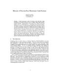
3 2500 / Tape& Reel75H For information on tape and reel specifications, including part orientation and tape sizes, please refer to our Tape and Reel Packaging SpecificationBrochure, BRD8011 5x5, 485 CEMARKING DIAGRAMNCP81239 AWLYYWWGG1A= Assembly LocationWL= Wafer LotYY= YearWW= Work WeekG= Pb Free Package(Note: Microdot may be in either location)321 Typical Application Notebooks, Tablets, Desktops All in Ones Monitors, TVs, and Set Top Boxes Consumer Electronics Car Chargers Docking Stations Power Banks81239 AAWLYYWWGG1 NCP81239, 1. Typical Application CircuitCS1CS2 CLINDSDASCLVDRVINTFLAGI2 CCurret Limit IndicatorInterruptV1V2 HSG1 HSG2 BST2 LSG1 LSG2 CSP1 FBVSW1 VSW2 BST1 CSN1 CSP2 CFET1 COMPPGND1 PGND2 AGNDS1S2S3S4CB1CB2 CPCCRCCO2Q5 EnableVCCDBIN5V RailENPDRVCVCCCVDRVDBOUTCO1Q6 RPURPDRCS1 RCS2 RDRVR sense2 Rsense1L1 Dead Battery /VCONNC urrent Sense 1 Current Sense 2 CSN2V1 VBUSF igure 2.
4 Pinout1718192021222324151413121110916 HSG2 LSG2 CSN2 CSP2 FBCS2 PGND2 PDRVENCOMPINTSDASCLAGNDAGNDCFET12345678 HSG1 LSG1 CSP1 CSN1V1 PGND1 CLINDCS13130292827262532 DBOUTVSW2 VSW1 BST2 BST1 VDRVVCCDBINE xposed Thermal PadNCP81239, 3. Block DiagramStartupINPUTUVLO_+_+ +Error OTA500 S/100 SCO2 BST1 HSG1 VSW1 LSG1 VDRVPGND1 LSG2 VDRVPGND2 BST2 HSG2 VSW2 NOLD riveLogic_2 NOLD riveLogic_1 CSN1 CSP1V1+_CSP2 CSN2 VCCVDRVCS1CS2CS1CS1CS2CS2 NCCLINDINTSDASCLL imitRegistersStatusRegistersI2 CInterfaceDigitalConfigurationOscillator ReferenceINTI nterfaceVFBCOMP +CCRCCP CS2_INTCS2_INT CS1_INTCS1_INT0_RampBuck LogicBoost LogicBuck BoostLogicCONFIGCONFIGSW1SW2SW3SW4 VDRVCFETDBINC urrent LimitingCircuitFor Dead BatteryCONFIGVFBPGT hermalShutdownTSControlLogicSW1SW2SW3SW4 IUVLOBBGIUVLOBPGTSCLINDBG+ CLINDP1 CLIMP1 + +CL2 PCL2P REFCS2_INTCL2CL1 BGValueRegisterADCCSP1CS1_INTCS2_INTA nalogMuxAGNDFLAG+ CLINDP2 CLIMP2 CLINDVCCENLOGICENPOLEN_MASK +VFBPG_LowPG_High +PGVFBPG_MSKOV_REFOVPG/OV/LOGICOV_MSK +COVDRV+ CL2N REFCL2 NCONFIGCONFIG +CL1 PCL1P REFCS1_INT+ CL1N REFCL1
5 NCONFIGCS1_INT0_RampVDRVPDRVCFETPDRVQ2V1 + + +Boot1 VBoot1 _UVLO+Boot1 VBoot2 _UVLOQ1V2 DBOUTV1FB180_RampRamp_0 Ramp_180 CSP1 CSN2 VFBPDRVCFETT able 1. PIN FUNCTION DESCRIPTIONPinPin NameDescription1 HSG1S1 gate drive. Drives the S1 N channel MOSFET with a voltage equal to VDRV superimposed on the switchnode voltage the gate of the S2 N channel MOSFET between ground and , 22 PGNDP ower ground for the low side MOSFET drivers. Connect these pins closely to the source of the bottomN channel terminal of the current sense terminal of the current sense voltage of the converter7CS1 Current sense amplifier output. CS1 will source a current that is proportional to the voltage across RS1 to anexternal resistor. CS1 voltage can be monitored with a high impedance input. Ground this pin if not drain output to indicate that the CS1 or CS2 voltage has exceeded the I2C programmed interface data interface clock is an open drain output that indicates the state of the output Power , the internal thermal trip, and oth-er I2C programmable drive of an external MOSFET that connects a bulk output capacitor to the output of the Power converter.
6 Necessary to adhere to low capacitance limits of the standard USB Specifications for Power prior toUSB PD 14 AGNDThe ground pin for the analog of the transconductance amplifier used for stability in closed loop , 1. PIN FUNCTION DESCRIPTIONPinDescriptionPin Name16 ENPrecision enable starts the part and places it into default configuration when open drain output used to control a sense amplifier output. CS2 will source a current that is proportional to the voltage across RS2 to anexternal resistor. CS2 voltage can be monitored with a high impedance input. Ground this pin if not voltage of the output, negative terminal of the gm terminal of the current sense terminal of the current sense the gate of the S3 N channel MOSFET between ground and gate drive. Drives the S4 N channel MOSFET with a voltage equal to VDRV superimposed on the switchnode voltage Driver Supply.
7 The BST2 pin swings from a diode voltage below VDRV up to a diode voltagebelow VOUT + VDRV. Place a mF capacitor from this pin to Node. VSW2 pin swings from a diode voltage drop below ground up to output output of the dead battery circuit which can also be used for the VCONN voltage dead battery input to the converter where 5 V is applied. A 1 mF capacitor should be placed close to thepart to decouple this voltage supply to the driver circuits. A 1 mF capacitor should be placed close to the part to decouplethis VCC pin supplies Power to the internal circuitry. The VCC is the output of a linear regulator which is pow-ered from V1. Pin should be decoupled with a 1 mF capacitor for stable Node. VSW1 pin swings from a diode voltage drop below ground up to Supply. The BST1 pin swings from a diode voltage below VDRV up to a diode voltage below V1 +VDRV.
8 Place a mF capacitor from this pin to Thermal Pad. Connect to AGND 2. MAXIMUM RATINGS Over operating free air temperature range unless otherwise notedRatingSymbolMinMaxUnitInput of the Dead Battery CircuitDBIN of the Dead Battery CircuitDBOUT Input VoltageVDRV Regulator OutputVCC of Current Sense AmplifiersCS1, CS2 Limit IndicatorCLIND + IndicatorINT + InputEN Communication LinesSDA, SCL + OutputCOMP + Power Stage Input VoltageV1 V, 40 V (20 ns)VPositive Current SenseCSP1 V, 40 V (20 ns)VNegative Current SenseCSN1 V, 40 V (20 ns)VPositive Current SenseCSP2 V, 40 V (20 ns)VNegative Current SenseCSN2 V, 40 V (20 ns)VFeedback VoltageFB DriverCFET + , 2. MAXIMUM RATINGS Over operating free air temperature range unless otherwise notedRatingUnitMaxMinSymbolDriver 1 and Driver 2 Positive RailsBST1,BST2 V wrt/PGND V wrt/VSW37 V, 40 V (20 ns) V wrt/VSWVHigh Side Driver 1 and Driver 2 HSG1,HSG2 V wrt/PGND V wrt/VSW37 V, 40 V (20 ns) V wrt/VSWVS witching Nodes and Return Path of Driver 1 and Driver 2 VSW1,VSW2 V32 V, 40 V (20 ns)VLow Side Driver 1 and Driver 2 LSG1,LSG2 DriverPDRV V, 40 V (20 ns)VVoltage DifferentialAGND toPGND CSN1, CSP2 CSN2 Differential VoltageCS1 DIF,CS2 DIF Maximum CurrentPDRVI010mAPDRV Maximum Pulse Current (100 ms on time, with > 1 s interval)PDRVIPUL0200mAMaximum VCC CurrentVCCI080mAOperating Junction Temperature Range (Note 1)
9 TJ 40150 COperating Ambient Temperature RangeTA 40100 CStorage Temperature RangeTSTG 55150 CThermal Characteristics (Note 2)QFN 32 5mm x 5mmMaximum Power Dissipation @ TA = 25 CMaximum Power Dissipation @ TA = 85 CThermal Resistance Junction to Air with SolderThermal Resistance Junction to Case Top with SolderThermal Resistance Junction to Case Bottom with C/W C/W C/WLead Temperature Soldering (10 sec):Reflow (SMD styles only) Pb Free (Note 3)RF260 Peak CStresses exceeding those listed in the Maximum Ratings table may damage the device. If any of these limits are exceeded, device functionalityshould not be assumed, damage may occur and reliability may be The maximum package Power dissipation limit must not be The value of QJA is measured with the device mounted on a 3in x 3in, 4 layer, inch FR 4 board with oz.
10 Copper on the top andbottom layers and ounce copper on the inner layers, in a still air environment with TA = 25 60 180 seconds minimum above 237 , 3. RECOMMENDED OPERATION RATINGSR atingSymbolValueUnitsMinMaxDriver Input Regulator Limit IndicatorCLIND + IndicatorINT + InputEN Communication LinesSDA, SCL + OutputCOMP + Stage Input Voltage to Side Current Sense PinsCSP1, CSN1 Side Current Sense PinsCSP2, CSN2 Positive Rails to PGNDBST1, BST2 Side Driver 1 and 2 HSG1, HSG2 Nodes and Return Path of Driver 1 and 2 to PGNDVSW1, VSW2 228 VLow Side Driver 1 and 2 LSG1, LSG2 VoltageFB DifferentialAGND to PGND CSN1, CSP2 CSN2 Differential VoltageCS1DF, CS2DF Junction Temperature RangeTJ 40150 COperating Ambient Temperature RangeTA 40100 CFunctional operation above the stresses listed in the Recommended Operating Ranges is not implied.