Transcription of NTMFS5C430NL MOSFET – Power, Single, N-Channel
1 NTMFS5C430NL . MOSFET Power, Single, N-Channel 40 V, mW, 200 A. Features Small Footprint (5x6 mm) for Compact Design Low RDS(on) to Minimize conduction losses Low QG and Capacitance to Minimize Driver losses V(BR)DSS RDS(ON) MAX ID MAX. These Devices are Pb Free and are RoHS Compliant mW @ 10 V. 40 V 200 A. mW @ V. MAXIMUM RATINGS (TJ = 25 C unless otherwise noted). Parameter Symbol Value Unit Drain to Source Voltage VDSS 40 V D (5). Gate to Source Voltage VGS 20 V. Continuous Drain TC = 25 C ID 200 A. Current RqJC. (Notes 1, 3) Steady TC = 100 C 140. G (4). State Power Dissipation TC = 25 C PD 110 W. RqJC (Note 1). TC = 100 C 53 S (1,2,3). Continuous Drain TA = 25 C ID 38 A. N CHANNEL MOSFET . Current RqJA. (Notes 1, 2, 3) Steady TA = 100 C 27. State Power Dissipation TA = 25 C PD W.
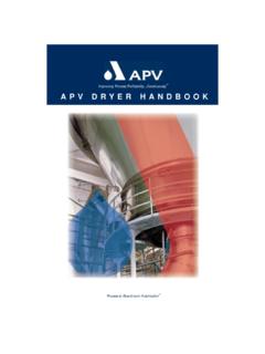
2 RqJA (Notes 1 & 2). MARKING. TA = 100 C DIAGRAM. Pulsed Drain Current TA = 25 C, tp = 10 ms IDM 900 A D. 1. Operating Junction and Storage Temperature TJ, Tstg 55 to C S D. +175 DFN5 S 5C430L. (SO 8FL) S AYWZZ. Source Current (Body Diode) IS 120 A CASE 488AA G D. Single Pulse Drain to Source Avalanche EAS 493 mJ STYLE 1 D. Energy (IL(pk) = 15 A). 5C430L = Specific Device Code Single Pulse Drain to Source Voltage VDSM 48 V A = Assembly Location (tp = 10 ms). Y = Year Lead Temperature for Soldering Purposes TL 260 C W = Work Week (1/8 from case for 10 s) ZZ = Lot Traceability Stresses exceeding those listed in the Maximum Ratings table may damage the device. If any of these limits are exceeded, device functionality should not be assumed, damage may occur and reliability may be affected.
3 ORDERING INFORMATION. THERMAL RESISTANCE MAXIMUM RATINGS See detailed ordering, marking and shipping information on page 5 of this data sheet. Parameter Symbol Value Unit Junction to Case Steady State RqJC C/W. Junction to Ambient Steady State (Note 2) RqJA 40. 1. The entire application environment impacts the thermal resistance values shown, they are not constants and are only valid for the particular conditions noted. 2. Surface mounted on FR4 board using a 650 mm2, 2 oz. Cu pad. 3. Maximum current for pulses as long as 1 second is higher but is dependent on pulse duration and duty cycle. Semiconductor Components Industries, LLC, 2016 1 Publication Order Number: May, 2019 Rev. 3 NTMFS5C430NL /D. NTMFS5C430NL . ELECTRICAL CHARACTERISTICS (TJ = 25 C unless otherwise specified).
4 Parameter Symbol Test Condition Min Typ Max Unit OFF CHARACTERISTICS. Drain to Source Breakdown Voltage V(BR)DSS VGS = 0 V, ID = 250 mA 40 V. Drain to Source Breakdown Voltage V(BR)DSS/ mV/ C. Temperature Coefficient TJ. Zero Gate Voltage Drain Current IDSS VGS = 0 V, TJ = 25 C 10. VDS = 40 V mA. TJ = 125 C 250. Gate to Source Leakage Current IGSS VDS = 0 V, VGS = 20 V 100 nA. ON CHARACTERISTICS (Note 4). Gate Threshold Voltage VGS(TH) VGS = VDS, ID = 250 mA V. Threshold Temperature Coefficient VGS(TH)/TJ mV/ C. Drain to Source On Resistance RDS(on) VGS = 10 V ID = 50 A mW. VGS = V ID = 50 A Forward Transconductance gFS VDS = 15 V, ID = 50 A 180 S. CHARGES, CAPACITANCES & GATE RESISTANCE. Input Capacitance CISS 4300 4942. Output Capacitance COSS VGS = 0 V, f = 1 MHz, VDS = 20 V 1900 2850 pF.
5 Reverse Transfer Capacitance CRSS 72 144. Total Gate Charge QG(TOT) VGS = V, VDS = 20 V; ID = 50 A 32 45. Total Gate Charge QG(TOT) VGS = 10 V, VDS = 20 V; ID = 50 A 70 82. Threshold Gate Charge QG(TH) 10 nC. Gate to Source Charge QGS 12 15. VGS = V, VDS = 20 V; ID = 50 A. Gate to Drain Charge QGD 16. Plateau Voltage VGP V. SWITCHING CHARACTERISTICS (Note 5). Turn On Delay Time td(ON) 15 28. Rise Time tr VGS = V, VDS = 20 V, 140 273. ns Turn Off Delay Time td(OFF) ID = 50 A, RG = W 31 67. Fall Time tf 9 19. DRAIN SOURCE DIODE CHARACTERISTICS. Forward Diode Voltage VSD VGS = 0 V, TJ = 25 C V. IS = 50 A TJ = 125 C Reverse Recovery Time tRR 61 77. Charge Time ta VGS = 0 V, dIs/dt = 100 A/ms, 29 38 ns Discharge Time tb IS = 50 A 32 50. Reverse Recovery Charge QRR 80 92 nC.
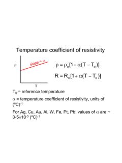
6 Product parametric performance is indicated in the Electrical Characteristics for the listed test conditions, unless otherwise noted. Product performance may not be indicated by the Electrical Characteristics if operated under different conditions. 4. Pulse Test: pulse width v 300 ms, duty cycle v 2%. 5. Switching characteristics are independent of operating junction temperatures. 2. NTMFS5C430NL . TYPICAL CHARACTERISTICS. 280 280. VDS = 5 V. 240 V to V 240. 10 V. ID, DRAIN CURRENT (A). ID, DRAIN CURRENT (A). 200 200. V. 160 160. 120 V 120. TJ = 25 C. 80 V 80. 40 V 40. TJ = 125 C TJ = 55 C. 0 0. 1 2 3 4. VDS, DRAIN TO SOURCE VOLTAGE (V) VGS, GATE TO SOURCE VOLTAGE (V). Figure 1. On Region Characteristics Figure 2. Transfer Characteristics RDS(on), DRAIN TO SOURCE RESISTANCE (mW).
7 RDS(on), DRAIN TO SOURCE RESISTANCE (mW). TJ = 25 C. TJ = 25 C. ID = 50 A VGS = V. VGS = 10 V. 0. 20 60 100 140 180 220 260. VGS, GATE VOLTAGE (V) ID, DRAIN CURRENT (A). Figure 3. On Resistance vs. Gate to Source Figure 4. On Resistance vs. Drain Current and Voltage Gate Voltage 100000. VGS = 10 V. RDS(on), NORMALIZED DRAIN TO . ID = 50 A TJ = 175 C. SOURCE RESISTANCE. 10000. IDSS, LEAKAGE (nA). TJ = 125 C. 1000. TJ = 85 C. 100. 10. 50 25 0 25 50 75 100 125 150 175 0 10 20 30 40. TJ, JUNCTION TEMPERATURE ( C) VDS, DRAIN TO SOURCE VOLTAGE (V). Figure 5. On Resistance Variation with Figure 6. Drain to Source Leakage Current Temperature vs. Voltage 3. NTMFS5C430NL . TYPICAL CHARACTERISTICS. 10000. VGS, GATE TO SOURCE VOLTAGE (V). CISS 10 QT. COSS. C, CAPACITANCE (pF). 8.
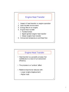
8 1000. 6. CRSS QGS QGD. 4. 100. VGS = 0 V 2 VDS = 20 V. TJ = 25 C TJ = 25 C. f = 1 MHz ID = 50 A. 10 0. 0 10 20 30 40 0 10 20 30 40 50 60 70. VDS, DRAIN TO SOURCE VOLTAGE (V) QG, TOTAL GATE CHARGE (nC). Figure 7. Capacitance Variation Figure 8. Gate to Source Voltage vs. Total Charge tr IS, SOURCE CURRENT (A). tf TJ = 125 C. td(on). t, TIME (ns). td(off). TJ = 25 C. VGS = V. VDD = 20 V TJ = 55 C. ID = 50 A. 1 10 100 RG, GATE RESISTANCE (W) VSD, SOURCE TO DRAIN VOLTAGE (V). Figure 9. Resistive Switching Time Variation Figure 10. Diode Forward Voltage vs. Current vs. Gate Resistance 1000 100. ID, DRAIN CURRENT (A). 100. TJ = 25 C. TJ = 100 C. IPEAK, (A). 10 TC = 25 C 10. 500 ms VGS 10 V. Single Pulse 1 ms 1. RDS(on) Limit Thermal Limit 10 ms Package Limit 1. 1 10 100 1E 4 1E 3 10E 2.
9 VDS (V) TIME IN AVALANCHE (s). Figure 11. Safe Operating Area Figure 12. IPEAK vs. Time in Avalanche 4. NTMFS5C430NL . TYPICAL CHARACTERISTICS. 100. 50% Duty Cycle 10 20%. 10%. RqJA ( C/W). 5%. 1 2%. 1%. Single Pulse 1 10 100 1000. PULSE TIME (sec). Figure 13. Thermal Characteristics DEVICE ORDERING INFORMATION. Device Marking Package Shipping . NTMFS5C430 NLT1G 5C430L DFN5 1500 / Tape & Reel (Pb Free). NTMFS5C430 NLT3G 5C430L DFN5 5000 / Tape & Reel (Pb Free). For information on tape and reel specifications, including part orientation and tape sizes, please refer to our Tape and Reel Packaging Specifications Brochure, BRD8011/D. 5. MECHANICAL CASE OUTLINE. PACKAGE DIMENSIONS. DFN5 5x6, (SO 8FL). CASE 488AA. 1 ISSUE N. SCALE 2:1 DATE 25 JUN 2018. 2X NOTES: 1. DIMENSIONING AND TOLERANCING PER.
10 C ASME , 1994. 2. CONTROLLING DIMENSION: MILLIMETER. D A 3. DIMENSION D1 AND E1 DO NOT INCLUDE. MOLD FLASH PROTRUSIONS OR GATE. 2 B BURRS. 2X. D1 MILLIMETERS. C DIM MIN NOM MAX. A A1 4X b E1 q c E D 2 D1 c D2 A1 E E1 1 2 3 4 E2 e BSC. TOP VIEW G C K SEATING L C DETAIL A PLANE L1 REF. M A q 0_ 12 _. C GENERIC. SIDE VIEW MARKING DIAGRAM*. DETAIL A. 1. b 8X XXXXXX. C A B AYWZZ. e/2. c e L. 1 4 XXXXXX = Specific Device Code A = Assembly Location K. Y = Year RECOMMENDED W = Work Week E2 SOLDERING FOOTPRINT* ZZ = Lot Traceability PIN 5 M 2X. (EXPOSED PAD) L1 *This information is generic. Please refer to 2X device data sheet for actual part marking. Pb Free indicator, G or microdot G , may or may not be present. Some products G D2 may not follow the Generic Marking. 2X. BOTTOM VIEW STYLE 1: STYLE 2: 2X.