Transcription of Oversampled ADCs Last Lecture - inst.eecs.berkeley.edu
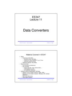
1 EECS 247 Lecture 23: Oversampling data Converters 2004H. K. Page 1EE247 Lecture 23 Oversampled ADCs 1-Bit quantization Quantization error spectrum SQNR analysis Limit cycle oscillations 2ndorder modulator Dynamic range Practical implementation Effect of various nonidealities on the performanceEECS 247 Lecture 23: Oversampling data Converters 2004H. K. Page 2 Oversampled ADCsLast Lecture Why Oversampling? Allows trading speed for resolution Relaxed transition band requirements for analog anti-aliasing filters Reduced baseband quantization noise power Utilizes low cost, low power digital filtering Issue of limit cycle oscillation (spurious inband tones) By simply increasing oversampling ratio: 2X increase in sampling ratio increase in resolution To achieve greater improvement in resolution: Embed quantizer in a feedback loop Predictive (delta modulation) Noise shaping (sigma delta modulation)EECS 247 Lecture 23: Oversampling data Converters 2004H.
2 K. Page 3 Oversampling A/D Conversion Analog front-end Oversampled noise-shaping modulator Converts original signal to a 1-bit digital output at the high rate of (2MX fsignal) Digital back-end digital filter Removes out-of-band quantization noise Provides anti-aliasing to allow re-sampling @ lower sampling rate1-bit@ fsn-bit@ fs/MSignal BW=fs/2 MEECS 247 Lecture 23: Oversampling data Converters 2004H. K. Page 4 Oversampled ADCP redictive Coding Quantize the difference signal rather than the signal itself Smaller input to ADC Buy dynamic range Only works if combined with oversampling 1-Bit digital output Digital filter computes average n-Bit output +_vINdOUTP redictorADCEECS 247 Lecture 23: Oversampling data Converters 2004H.
3 K. Page 5 Oversampled ADCD ecimator: Digital (low-pass) filter Removes quantization error for f > B Provides most anti-alias filtering Narrow transition band, high-order 1-Bit input, N-Bit output (essentially computes average )fs= MfNFreqBSignal wide narrow transitionfs1= M fNDSPM odulatorDigitalAA-Filterfs2= fN+ 1-Bit DigitalN-BitDigitalEECS 247 Lecture 23: Oversampling data Converters 2004H. K. Page 6 Modulator Objectives: Convert analog input to 1-Bit pulse density stream Move quantization error to high frequencies f >>B Operates at high frequency fs>> fN M = 8 .. 256 (typical)..1024 Better be simple = ModulatorEECS 247 Lecture 23: Oversampling data Converters 2004H. K. Page 7 Sigma-Delta ModulatorsAnalog 1-Bit modulators convert a continuous time analog input vINinto a 1-Bit sequence dOUTH(z)+_vINdOUTLoop filter1b Quantizer (a comparator)fsDACEECS 247 Lecture 23: Oversampling data Converters 2004H.
4 K. Page 8 Sigma-Delta Modulators The loop filter H can be either a switched-capacitor or continuous time Switched-capacitor filters are easier to implement and scale with the clock rate Continuous time filters provide anti-aliasing protection Can be realized with passive LC s at very high frequenciesH(z)+_vINdOUTfsDACEECS 247 Lecture 23: Oversampling data Converters 2004H. K. Page 91stOrder ModulatorIn a 1storder modulator, simplest loop filter an integrator+_vINdOUT H(z) =z-11 z-1 DACEECS 247 Lecture 23: Oversampling data Converters 2004H. K. Page 101stOrder ModulatorSwitched-capacitor implementationVi-+ 1 2 21,0dOUT+ /2- /2 EECS 247 Lecture 23: Oversampling data Converters 2004H. K. Page 111stOrder Modulator Properties of the first-order modulator: Analog input range is equal to the DAC reference The average value of dOUTmust equal the average value of vIN +1 s (or 1 s) density in dOUTis an inherently monotonic function of vIN linearity is not dependent on component matching Alternative multi-bit DAC (and ADCs) solutions reduce the quantization error but loose this inherent monotonicity+_vINdOUT - /2 vIN + /2 DAC- /2or + /2 EECS 247 Lecture 23: Oversampling data Converters 2004H.
5 K. Page 121stOrder Modulator3Y2Q1 XSine Wavez -11-z -1 IntegratorComparatorInstantaneous quantization errorTally of quantization error1-Bitquantizer1-Bit digital output stream,-1, +1 Implicit 1-Bit DAC+ /2, - /2 ( = 2)Analog input- /2 Vin + /2 EECS 247 Lecture 23: Oversampling data Converters 2004H. K. Page 131stOrder Modulator SignalsT = 1/fs= 1/ (M fN)Xanalog inputQtally of q-errorYdigital/DAC outputMean of Y approximates [ t/T ]Amplitude1st Order Sigma-DeltaXQYEECS 247 Lecture 23: Oversampling data Converters 2004H. K. Page 14 Modulator Characteristics Quantization noise and thermal noise (KT/C) distributed over fs/2 to +fs/2 Total noise reduced by 1/M Very high SQNR achievable (> 20 Bits!)
6 Inherently linear for 1-Bit DAC Quantization error independent of component matching Limited to moderate to low speedEECS 247 Lecture 23: Oversampling data Converters 2004H. K. Page [ f/fs ]Amplitude [ dBWN ]First order sigma-delta, A= , fx= , offset= , N=1024, K=30 Output Spectrum Definitely not white! Skewed towards higher frequencies Tones dBWN (dB White Noise) scale sets the 0dB line at the noise per bin of a random -1, +1 sequence 247 Lecture 23: Oversampling data Converters 2004H. K. Page 16 Quantization Noise Analysis Sigma-Delta modulators are nonlinear systems with memory very difficult to analyze directly Representing the quantizer as an additive noise source linearizes the systemIntegrator QuantizerModelQuantizationError e(kT)x(kT)y(kT)11H()1zzz =+ EECS 247 Lecture 23: Oversampling data Converters 2004H.
7 K. Page 17 Signal Transfer Function()110H()1zzzHjj =+=Signal transfer function low pass function:IntegratorH(z) x(kT)y(kT)-FrequencyMagnitudef0()()011 1()() Delay()1()SigSigHjsYzHzHzzXzHz =+=== +EECS 247 Lecture 23: Oversampling data Converters 2004H. K. Page 18 Noise Transfer FunctionQualitative Analysis2eqv220nfvf vi-vo0j 2220eqnfvvf = vi-vo0j Frequencyf02nv vi-vo0j 220eqnfvvf = EECS 247 Lecture 23: Oversampling data Converters 2004H. K. Page 19 STF and NTFS ignal transfer function:1()()STF Delay()1()YzHzzXzHz === +Noise transfer function:erentiator Diff 1)(11)()(NTF1 =+== zzHzEzYIntegrator QuantizerModelQuantizationError e(kT)x(kT)y(kT)11H()1zzz =+ EECS 247 Lecture 23: Oversampling data Converters 2004H.
8 K. Page 20 Noise Transfer Function()()()()()()1/2/2/2/2/2/2/2()11 ()1()()(1 )=222sin/22sin/22sin/2where 1/Thus: ()=2sin/2=2sin/ ()jTjTjTjTjTjTjjTssyYzNTFzEzHzeeNTFjeeej TeeTTeTfNTFfTffNf === + = == = ==2()()eNTFfNfEECS 247 Lecture 23: Oversampling data Converters 2004H. K. Page 21 First Order ModulatorNoise Transfer Characteristics()22()()()4sin/yesNfNTFfN fff ==EECS 247 Lecture 23: Oversampling data Converters 2004H. K. Page 22 First Order ModulatorSimulatedNoise Transfer [f/fs] Amplitude [ dBWN ]Sin input, A= , fx= , offset= , N=1024, K=30output spectrumNTFS ignalEECS 247 Lecture 23: Oversampling data Converters 2004H. K. Page 23 Quantizer Error For quantizers with many bits Let s use the same expression for the 1-Bit case Only simulation can tell if the result is usefulExperience: Often sufficiently accurate to be useful, with enoughexceptions to be very careful()1222 =kTeEECS 247 Lecture 23: Oversampling data Converters 2004H.
9 K. Page 24In-Band Quantization Noise()()()()()()()22211122222223114sin/ for 112sin121312jfTfsMfsMsBYQzeBszHzzNTFzzNT FfffMSSfNTFzdffTdffM = = = =>>= EECS 247 Lecture 23: Oversampling data Converters 2004H. K. Page 25 Dynamic RangeMDR1633 dB3242 dB102487 dB222332322peak signal power10log10logpeak noise power1 sinusoidal input, == == == ==+ = ++ogM2X increase in M 9dB ( ) increase in DREECS 247 Lecture 23: Oversampling data Converters 2004H. K. Page 26 Oversampling and Noise Shaping modulators have interesting characteristics Unity gain for input signal VIN Large attenuation of quantization noise injected at quatizer input Performance significantly better than 1-Bit noise performance possible for frequencies << fs Oversampling (M = fs/fN> 1) improves SQNR considerably 1st-Order : DR increases 9dB for each doubling of M SQNR independent of circuit complexity and accuracy Analysis assumes that the quantizer noise is white Not true in practice, especially for low-order modulators Practical modulators suffer from other noise sources also ( thermal noise)EECS 247 Lecture 23: Oversampling data Converters 2004H.
10 K. Page 27DC Input DC input A = 1/11 Doesn t look like spectrum of DC at all Tones frequency shape the same as quantization noise more prominent at higher frequencies Quantization noise is [ f/fs]Amplitude [ dBWN ]First order sigma-delta, DC input, offset= , N=1024, K=30 EECS 247 Lecture 23: Oversampling data Converters 2004H. K. Page 28 Limit [t/T]OutputFirst order sigma-delta, DC input-111+110-19+18-17+16-15+14-13+12+11 DC input 1/11 Periodic sequence:EECS 247 Lecture 23: Oversampling data Converters 2004H. K. Page 29 Limit CycleIn-band spurious tone with f ~ DC input Problem: quantization noise is periodic Solution: Dither: randomizes quantization noise-thermal noise dither Second order loopEECS 247 Lecture 23: Oversampling data Converters 2004H.