Transcription of Stepper motor - Beckhoff
1 I/OMotion ControlApplication Note DK9222-0410-0014 KeywordsStepper motorFieldbusMicrosteppingEncoderPhase currentTravel distance controlSpeed interfaceKL2531KL2541 Stepper motorPart A of this Application Example provides general information on Stepper motors (design, areas of application, control, etc.), while part B describes the functionality of the KL2531 and KL2541 Stepper motor terminals from Beckhoff and provides application examples for simple travel distance control at a PLC and for a speed interface via General information on Stepper motorsStepper motors are special versions of the synchronous machine, in which the rotor is a permanent magnet, while the stator consists of a coil package. In contrast to synchronous motors, Stepper motors have a large number of pole pairs. motor operation requires a control unit, which energises the individual motor windings based on a certain pulse sequence. A Stepper motor has a tendency to mechanical oscillation. Above its load limit it loses dynamic characteristics and may lose individual steps.
2 Under high load the shaft may even stop. Safe positioning is therefore only guaranteed within the performance limits. If the motor is operated within its load limits, positioning without feedback of the rotor position can be achieved by linking individual steps. This operating mode (open loop control) and the durability of the Stepper motor enable it to be used as a positioning drive in price-sensitive Basic function principles of a Stepper motorLike most electric motors, a Stepper motor consists of a stator (fixed external winding) and a rotor (rotating shaft with magnets). The rotation of the motor shaft (rotor) is generated by rapid energising the electromagnetic field of the stator, causing the shaft to turn by the step angle a. In a minimum control configuration, the Stepper motor is moved from pole to pole, or from step to step. A full turn of the motor shaft is therefore made up of individual steps. Energising of the motor windings results in a magnetic field in the motor from north to south (or south to north if the power supply has negative polarity and the winding is arranged accordingly).
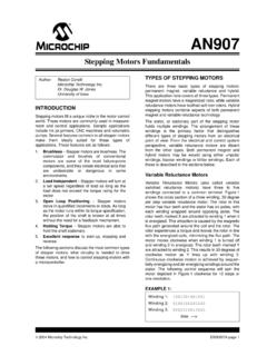
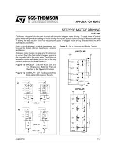
3 The movable stator with its permanent magnets aligns itself according to the direction of the external magnetic field of the Automation TechnologyBeckhoff1 For application notes see disclaimer on the last pageI/OMotion ControlApplication Note DK9222-0410-0014 Basic Stepper motor typesStepper motors come in numerous varieties, which tend to be based on three basic types:1 Variable reluctance ( Stepper ) motor (VR)2 Permanent magnet Stepper motor , claw-poled PM motor , Tin-Can- motor (PM) 3 Hybrid Stepper motor (HY) W2W2W1W1 SNNNNNSSSW1W2W2W2W2W1W1W1 StatorRotorWindingABCDA B C D S1) VR2) PM3) HYFig. 1 Basic Stepper motor types: reluctance Stepper motor , permanent magnet Stepper motor , and hybrid Stepper motorVariable Reluctance Stepper motor (Fig. 1, left)The rotor consists of a magnetically soft material with different tooth pitch compared with the pole pitch of the stator. When a phase element is excited the rotor assumes a position in which the magnetic resistance (reluctance) for the excited magnetic circuit is at a minimum.
4 Movement of the rotor causes a torque that returns the rotor to its original position. The stator requires at least two phase windings in order to achieve a change in the direction of rotation. Due to the different tooth pitch of the pole and the rotor, the direction of the rotating field is opposite to the direction of rotation of the rotor. In de-energised state the motor has no holding magnet Stepper motor /claw-pole Stepper motor (Fig. 1, centre)A permanent magnet Stepper motor consists of a stator with individually controllable windings and a rotor with a permanent magnet. The rotor may be configured as a cylindrical ferrite rod with multi-pole magnetisation along its circumference. The permanent-magnetic rotor always aligns itself with the right polarity relative to the stator winding. Permanent magnet Stepper motors have a holding torque to which a non-energised motor can be subjected without causing a continuous rotation. New Automation TechnologyBeckhoff2 For application notes see disclaimer on the last pageI/OMotion ControlApplication Note DK9222-0410-0014 Hybrid Stepper motor (Fig.)
5 1, right)Combination of VR (small step angles) and PM (high torque, holding torque). The rotor consists of a permanent magnet arranged in axial direction and positioned between two magnetically soft toothed discs. The toothed discs are offset by half a tooth pitch. Due to the arrangement of the permanent magnets in the rotor one of the toothed discs forms the north pole, the other the south pole of the rotor. The rotor teeth align themselves with the stator teeth, depending on which stator phase is Special featuresResonanceIrregular operation in certain speed ranges, usually in combination without coupled load, indicates that the Stepper motor runs at its resonance frequency. The motor may even stop. A distinction can be made between resonances in the lower frequency range up to approx. 250 Hz and resonances in the medium to upper frequency range: Medium to high-frequency resonances are mainly caused by electrical parameters such as inductance of the motor winding and capacitances in the supply lines.
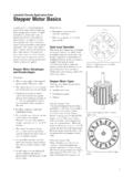
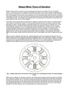
6 Due to the high frequency they have no significant effect on the torque and can be controlled relatively easily through appropriate timing. The resonances in the lower frequency range are mainly caused by mechanical parameters of the motor . In addition to irregular movement they also lead to significant loss of torque, which not only interferes with the application but may even obstruct it through loss of Automation TechnologyBeckhoff For application notes see disclaimer on the last pageI/OMotion ControlApplication Note DK9222-0410-0014 Rotor lengthRotor lengthStep sequenceStep sequenceRotor lengthStep sequenceRotor lengthStep sequenceMotor can no longer followFig. 2 Rotor position as a function of step sequenceIn principle, the Stepper motor represents an oscillatory system (comparable to a mass/spring system), consisting of the moving rotor with a moment of inertia and a magnetic field that creates a restoring force that acts on the rotor. Moving and releasing the rotor creates a damped oscillation.
7 Each current pulse leads to a transient phenomenon of the rotor position (Fig. 2, top left). With increasing frequency the transient phenomenon is superimposed by the subsequent pulse, resulting in smoothing of the speed curve (Fig. 2, top right and bottom left). If the control frequency matches the resonance frequency the oscillation is amplified, so that in the worst case the rotor can no longer follow the steps and starts oscillating between two positions (Fig. 2, bottom right).Heat generationStepper motors also draw their rated current when at a standstill, although in this case they cannot convert it into movement. This inevitably results in heating of the motor , and the motor temperature may be 100 C warmer than ambient, depending on the configuration. Many manufacturers recommended temperature Automation TechnologyBeckhoff4 For application notes see disclaimer on the last pageI/OMotion ControlApplication Note Advantages of Stepper motors compared with other motorsIn contrast to other motors Stepper motors have a high holding torque even at low speed, and even on standstill.
8 Another advantage is the simple control of Stepper motors: Alternate energising of the individual coils causes the motor to move step by step. The fixed number of steps per revolution always enables the current position to be determined if the steps are counted and the motor is operated within its performance limits. No encoder is required for simple positioning tasks within the performance limits. Stepper motors are therefore ideally suited as cost-effective solutions for simple positioning Areas of application for the different Stepper motor types1 PM: Technologically relatively simple solution for low-powered drives with low or medium requirements in terms of dynamics | Suitable for automotive and building automation (HVAC) applications2 VR:Less significant | can be produce economically | only achieves low efficiency | no holding torque | stronger tendency to mechanical vibrations than polarised Stepper motors HY:Best motor from an energy perspective with best performance parameters | above 100 cNm torque no improvement of the mass/performance ratio | small performance classes dominate in peripheral data processing devices (printers/scanners, etc.)
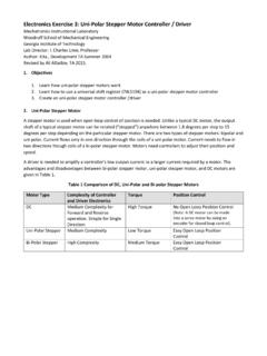
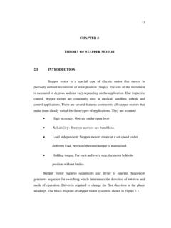
9 | higher performance classes typical for high-quality positioning tasks (robotics) Step angle in Typical versions are Stepper motors with the following parameters: Holding torque MH in Stepper Stepper motorHybrid Stepper motor Fig. 2. Basic control principles Since it is not sufficient to apply a constant supply voltage to the Stepper motor in order to generate a rotation of the shaft, the individual coils have to be energised alternately. To this end control electronics are required for setting the speed and direction. In addition, the control electronics must support the three different step patterns that are used for influencing the indexing position of the Automation TechnologyBeckhoff For application notes see disclaimer on the last pageI/OMotion ControlApplication Note Full step and half stepFull stepTwo adjacent windings are energised at any one time, so the rotor aligns itself centrally between the pole axes. In this way a high torque can be stepBetween two full step positions only one winding is energised, so that the step angle is halved at the expense of a smaller, non uniform torque.
10 Full step modeStep sequenceDirectionControl 1 Control 2 Control 3 Control 4l1l2 Half step modeControl 1 Control 2 Control 1 Control 4l1l2 Intermediate steps for half step modeFig. 4 Differences in the control modes for Stepper motors (left: full step, right: half step) MicrostepBoth in full step mode and in half step mode complete windings are energised based on a certain pulse pattern. The motor rotates suddenly by a fixed angle. In microstepping mode the control electronics generate a PWM with very fine resolution, so that the windings are supplied with a constant current flow in SinCos shape. In this mode the motor torque is directly related to the current Automation TechnologyBeckhoff For application notes see disclaimer on the last pageI/OMotion ControlApplication Note DK9222-0410-0014B Stepper motor terminals KL2 1 and KL2 41 from BeckhoffThe KL2531 and KL2541 Stepper motor terminals integrate a compact Motion Control solution for Stepper motors up to 200 W within a very small space, which can be used for direct control of unipolar and bipolar Stepper motors.