Transcription of TL594 Precision Switchmode Pulse Width …
1 Semiconductor Components Industries, LLC, 2005 November, 2005 Rev. 51 Publication Order Number: TL594 /DTL594 Precision SwitchmodePulse Width ModulationControl CircuitThe TL594 is a fixed frequency, Pulse Width modulation controlcircuit designed primarily for Switchmode power supply Complete Pulse Width Modulation Control Circuitry On Chip Oscillator with Master or Slave Operation On Chip Error Amplifiers On Chip V Reference, Accuracy Adjustable Deadtime Control Uncommitted Output Transistors Rated to 500 mA Source or Sink Output Control for Push Pull or Single Ended Operation Undervoltage Lockout Pb Free Packages are Available*MAXIMUM RATINGSR atingSymbolValueUnitPower Supply VoltageVCC42 VCollector Output VoltageVC1,VC242 VCollector Output Current(Each Transistor) (Note 1)IC1, IC2500mAAmplifier Input voltage RangeVIR to +42 VPower Dissipation @ TA 45 CPD1000mWThermal ResistanceJunction to Ambient (PDIP)Junction to Air (TSSOP)Junction to Ambient (SOIC)RqJA80140135 C/WOperating Junction TemperatureTJ125 CStorage Temperature RangeTstg 55 to +125 COperating Ambient Temperature RangeTL594CD, CN, CDTBTA 40 to 85 CDerating Ambient TemperatureTA45 CMaximum ratings are those values beyond which device damage can ratings applied to the device are individual stress limit values (notnormal operating conditions) and are not valid simultaneously.
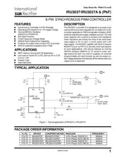
2 If these limits areexceeded, device functional operation is not implied, damage may occur andreliability may be Maximum thermal limits must be observed.*For additional information on our Pb Free strategy and soldering details, pleasedownload the ON Semiconductor Soldering and Mounting TechniquesReference Manual, 16D SUFFIXCASE 751 BTSSOP 16 DTB SUFFIXCASE 948F1 PDIP 16N SUFFIXCASE 64811 MARKINGDIAGRAMS116TL594 CDGAWLYWWA= Assembly LocationWL, L= Wafer LotYY, Y= YearWW, W = Work WeekG or G= Pb Free PackageTL594 DTBALYWGGSee detailed ordering and shipping information in the packagedimensions section on page 10 of this data INFORMATIONPIN CONNECTIONSCTRTG roundC11 InvInputC2Q2E2E11 VREF(Top View)NoninvInputInvInputVrefOutputContro lVCCN oninvInputCompen/PWNComp InputDeadtimeControlErrorAmp+ 23456789101112131415162 ErrorAmp+ Q1 (Note.)
3 Microdot may be in either location) TL594 OPERATING CONDITIONSC haracteristicsSymbolMinTypMaxUnitPower Supply Output VoltageVC1, VC2 3040 VCollector Output Current (Each transistor)IC1, IC2 200mAAmplified Input VCC Into Feedback Terminallfb Output Currentlref 10mATiming Input voltage (Pins 3, 4, 13) CHARACTERISTICS (VCC = 15 V, CT = mF, RT = 12 kW, unless otherwise noted.)For typical values TA = 25 C, for min/max values TA is the operating ambient temperature range that applies, unless otherwise SECTIONR eference voltage (IO = mA, TA = 25 C)(IO = mA) Regulation (VCC = V to 40 V)Regline Regulation (IO = mA to 10 mA)Regload Circuit Output Current (Vref = 0 V)ISC154075mAOUTPUT SECTIONC ollector Off State Current (VCC = 40 V, VCE = 40 V)IC(off) Off State Current (VCC = 40 V, VC = 40 V, VE = 0 V)IE(off) 100mACollector Emitter Saturation voltage (Note 1)Common Emitter (VE = 0 V, IC = 200 mA)Emitter Follower (VC = 15 V, IE = 200 mA)VSAT(C)VSAT(E) Control Pin CurrentLow State (VOC V)High State (VOC = Vref)IOCLIOCH 20mAOutput voltage Rise TimeCommon Emitter (See Figure 13)Emitter Follower (See Figure 14)
4 Tr 100100200200nsOutput voltage Fall TimeCommon Emitter (See Figure 13)Emitter Follower (See Figure 14)tf 4040100100nsERROR AMPLIFIER SECTIONI nput Offset voltage (VO (Pin 3) = V)VIO Offset Current (VO (Pin 3) = V)IIO Bias Current (VO (Pin 3) = V)IIB Common Mode voltage Range (VCC = 40 V, TA = 25 C)VICR0 to VCC Input voltage RangeVIR(INV) to VCC Loop voltage Gain (DVO = V, VO = V to V, RL = kW)AVOL7095 dBUnity Gain Crossover Frequency (VO = V to V, RL = kW)fC 700 kHzPhase Margin at Unity Gain (VO = V to V, RL = kW) m 65 Mode Rejection Ratio (VCC = 40 V)CMRR6590 dBPower Supply Rejection Ratio (DVCC = 33 V, VO = V, RL = kW)PSRR 100 dBOutput Sink Current (VO (Pin 3) = V)IO mAOutput Source Current (VO (Pin 3) = V)IO+ mA1. Low duty cycle Pulse techniques are used during test to maintain junction temperature as close to ambient temperature as CHARACTERISTICS (VCC = 15 V, CT = mF, RT = 12 kW, unless otherwise noted.)
5 For typical values TA = 25 C, for min/max values TA is the operating ambient temperature range that applies, unless otherwise COMPARATOR SECTION (Test Circuit Figure 11)Input Threshold voltage (Zero Duty Cycle)VTH Sink Current (VPin 3 = V)II mADEADTIME CONTROL SECTION (Test Circuit Figure 11)Input Bias Current (Pin 4) (VPin 4 = 0 V to V)IIB (DT) 10mAMaximum Duty Cycle, Each Output, Push Pull Mode(VPin 4 = 0 V, CT = mF, RT = 12 kW)(VPin 4 = 0 V, CT = mF, RT = 30 kW)DCmax45 484550 %Input Threshold voltage (Pin 4)(Zero Duty Cycle)(Maximum Duty Cycle)VTH VOSCILLATOR SECTIONF requency(CT = mF, RT = 30 kW)(CT = mF, RT = 12 kW, TA = 25 C)(CT = mF, RT = 12 kW, TA = Tlow to Thigh)fosc Deviation of Frequency* (CT = mF, RT = 30 kW) fosc %Frequency Change with voltage (VCC = V to 40 V, TA = 25 C)Dfosc (DV) Change with Temperature(DTA = Tlow to Thigh, CT = mF, RT = 12 kW)Dfosc (DT) %UNDERVOLTAGE LOCKOUT SECTIONTurn On Threshold (VCC Increasing, Iref = mA)TA = 25 CTA = Tlow to ,ITL594 MVH10050150150300300mVTOTAL DEVICES tandby Supply Current (Pin 6 at Vref, All other inputs and outputs open)(VCC = 15 V)(VCC = 40 V)ICC Supply Current (VPin 4 = V, CT = mF, RT = 12 kW,VCC = 15 V, See Figure 11) 11 mA*Standard deviation is a measure of the statistical distribution about the mean as derived from the formula, Nn = 1 (Xn X)2N 1TL594 1.
6 Representative Block DiagramFigure 2. Timing DiagramCapacitor CTFeedback/PWM ControlFlip FlopClock InputFlip FlopQFlip FlopQOutput Q1 EmitterOutput Q2 EmitterOutputControl6 RTCT54 DeadtimeControlOscillator +1 + ++2 DQCk ++ Amp1 Feedback PWMC omparator FlopOutput ControlError Amp2 DeadtimeComparatorPWMC omparatorQThis device contains 46 active INFORMATIOND escriptionThe TL594 is a fixed frequency Pulse Width modulationcontrol circuit, incorporating the primary building blocksrequired for the control of a switching power supply. (SeeFigure 1) An internal linear sawtooth oscillator is frequency programmable by two external components, RT and CT. Theapproximate oscillator frequency is determined by:fosc CTFor more information refer to Figure Pulse Width modulation is accomplished bycomparison of the positive sawtooth waveform acrosscapacitor CT to either of two control signals.
7 The NOR gates,which drive output transistors Q1 and Q2, are enabled onlywhen the flip flop clock input line is in its low state. Thishappens only during that portion of time when the sawtoothvoltage is greater than the control signals. Therefore, anincrease in control signal amplitude causes a correspondinglinear decrease of output Pulse Width . (Refer to the TimingDiagram shown in Figure 2.)The control signals are external inputs that can be fed intothe deadtime control, the error amplifier inputs, or thefeedback input. The deadtime control comparator has aneffective 120 mV input offset which limits the minimumoutput deadtime to approximately the first 4% of thesawtooth cycle time. This would result in a maximum dutycycle on a given output of 96% with the output controlgrounded, and 48% with it connected to the reference deadtime may be imposed on the output bysetting the deadtime control input to a fixed voltage ,ranging between 0 V to Pulse Width modulator comparator provides a meansfor the error amplifiers to adjust the output Pulse Width fromthe maximum percent on time, established by the deadtimecontrol input, down to zero, as the voltage at the feedbackpin varies from V to V.
8 Both error amplifiers have acommon mode input range from V to (VCC 2 V), andmay be used to sense power supply output voltage andcurrent. The error amplifier outputs are active high and areORed together at the noninverting input of the Pulse widthmodulator comparator. With this configuration, theamplifier that demands minimum output on time, dominatescontrol of the TableInput/OutputControlsOutput Functionfoutfosc=GroundedSingle ended PWM @ Q1 and @ VrefPush pull capacitor CT is discharged, a positive Pulse isgenerated on the output of the deadtime comparator, whichclocks the Pulse steering flip flop and inhibits the outputtransistors, Q1 and Q2. With the output control connectedto the reference line, the Pulse steering flip flop directs themodulated pulses to each of the two output transistorsalternately for push pull operation.
9 The output frequency isequal to half that of the oscillator. Output drive can also betaken from Q1 or Q2, when single ended operation with amaximum on time of less than 50% is required. This isdesirable when the output transformer has a ringbackwinding with a catch diode used for snubbing. When higheroutput drive currents are required for single endedoperation, Q1 and Q2 may be connected in parallel, and theoutput mode pin must be tied to ground to disable theflip flop. The output frequency will now be equal to that ofthe TL594 has an internal V reference capable ofsourcing up to 10 mA of load current for external biascircuits. The reference has an internal accuracy of a typical thermal drift of less than 50 mV over anoperating temperature range of 0 to 70 3.
10 Oscillator Frequency versusTiming k k k10 k20 k50 k100 k 200 k500 k MRT, TIMING RESISTANCE (W), OSCILLATOR FREQUENCY (Hz)fOSCCT = mFVCC = 15 mFFigure 4. Open Loop voltage Gain andPhase versus k10 k100 M, OPEN LOOP voltage GAIN (dB)VOLf, FREQUENCY (Hz)AVOL020406080100120140160180, EXCESS PHASE (DEGREES) VCC = 15 VDVO = VRL = kWA500 k100 k10 k5001201101009080706050403020100TL594 5. Percent Deadtime versusOscillator FrequencyFigure 6. Percent Duty Cycle versusDeadtime Control VoltageFigure 7. Emitter Follower ConfigurationOutput Saturation voltage versusEmitter k10 k100 k500 kfosc, OSCILLATOR FREQUENCY (Hz)% DT, PERCENT DEADTIME (EACH OUTPUT)CT = , DEADTIME CONTROL voltage (IV)% DC, PERCENT DUTY CYCLE (EACH OUTPUTVCC = 15 VVOC = Vref 1. CT = mF 1. RT = 10 kW 2. CT = mF 1. RT = 30 kW21 Figure 8.)