Transcription of AN460 APPLICATION NOTE - st.com
1 1/11AN460 APPLICATION NOTED ecember 2003 INTRODUCTIONOver the years while working with stepper motor users, many of the same questions keep occurring from noviceas well as experienced users of stepper motors. This APPLICATION note is intended as a collection of answers tocommonly asked questions about stepper motors and driver design. In addition the reference list contains anumber of other APPLICATION notes, books and articles that a designer may find useful in applying stepper the course of this discussion the reader will find references to the L6201, L6202 and L6203. Sincethese devices are the same die and differ only in package, any reference to one of the devices should be con-sidered to mean any of the three devices. motor Selection (Unipolar vs Bipolar) stepper motors in common use can be divided into general classes, Unipolar driven motors and Bipolar drivenmotors. In the past unipolar motors were common and preferred for their simple drive configurations.
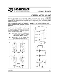
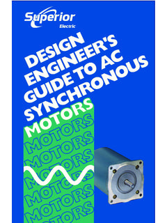
2 However, with the advent of cost effective integrated drivers, bipolar motors are now more common. These bipolar motorstypically produce a higher torque in a given form factor [1]. Drive Topology SelectionDepending on the torque and speed required from a stepper motor there are several motor drive topologiesavailable [5, chapter3]. At low speeds a simple direct voltage drive, giving the motor just sufficient voltage sothat the internal resistance of the motor limits the current to the allowed value as shown in Figure 1A, may besufficient. However at higher rotational speeds there is a significant fall off of torque since the winding induc-tance limits the rate of change of the current and the current can no longer reach it s full value in each step, asshown in Figure 2. Figure 1. Simple direct voltage unipolar motors Thomas L. HopkinsSTEPPER motor DRIVER CONSIDERATIONSCOMMON PROBLEMS & SOLUTIONSThis note explains how to avoid same of the more common pitfalls in motor drive design.
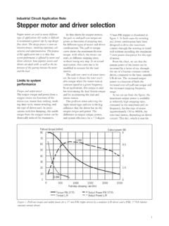
3 It is basedon the author s experience in responding to enquiries from the APPLICATION NOTE2/11 Figure 2. Direct voltage drive. A - low speed; B - too high speed generates fall of solution is to use what is commonly referred to as an L/nR drive (Fig. 1B). In this topology a higher voltageis used and the current limit is set by an external resistor in series with the motor winding such that the sum ofthe external resistance and the internal winding resistance limits the current to the allowed value. This drivetechnique increases the current slew rate and typically provides better torque at high rotational speed. Howeverthere is a significant penalty paid in additional dissipation in the external resistances. To avoid the additionaldissipation a chopping controlled current drive may be employed, as shown in Figure 3. In this technique thecurrent through the motor is sensed and controlled by a chopping control circuit so that it is maintained withinthe rated level.
4 Devices like the L297, L6506 and PBL3717A implement this type of control. This technique im-proves the current rise time in the motor and improves the torque at high speeds while maintaining a high effi-ciency in the drive [2]. Figure 4 shows a comparison between the winding current wave forms for the same motordriven in these three techniques. Figure 3. Chopper drive provides better 4. motor current using L/R, L/5R and chopper constant current APPLICATION NOTEIn general the best performance, in terms of torque, is achieved using the chopping current control technique[2]. This technique also allows easy implementation of multiple current level drive techniques to improve the mo-tor performance. [1]Driving a Unipolar motor with the L298N or L6202 Although it is not the optimal solution, design constraints sometimes limit the motor selection. In the case wherethe designer is looking for a highly integrated drive stage with improved performance over previous designs butis constrained to drive a unipolar wound (6 leaded) motor it is possible to drive the motor with H-Bridge driverslike the L298N or L6202.
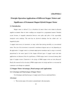
5 To drive such a motor the center tap of the motor should be left unconnected and thetwo ends of the common windings are connected to the bridge outputs, as shown in Figure 5. In this configura-tion the user should notice a marked improvement in torque for the same coil current, or put another way, thesame torque output will be achieved with a lower coil current. A solution where the L298N or L6202 is used todrive a unipolar motor while keeping the center connection of each coil connected to the supply will not , the protection diodes needed from collector to emitter (drain to source) of the bridge transistors will beforward biased by the transformer action of the motor windings, providing an effective short circuit across thesupply. Secondly the L298N, even though it has split supply voltages, may not be used without a high voltagesupply on the chip since a portion of the drive current for the output bridge is derived from this supply. Selecting Enable or Phase choppingWhen implementing chopping control of the current in a stepper motor , there are several ways in which the cur-rent control can be implemented.
6 A bridge output, like the L6202 or L298N, may be driven in enable chopping,one phase chopping or two phase chopping, as shown in Figure 6. The L297 implements enable chopping orone phase chopping, selected by the control input. The L6506 implements one phase chopping, with the recir-culation path around the lower half of the bridge, if the four outputs are connected to the 4 inputs of the bridgeor enable chopping if the odd numbered outputs are connected to the enable inputs of the bridge. Selecting thecorrect chopping mode is an important consideration that affects the stability of the system as well as the dissi-pation. Table 1 shows a relative comparison of the different chopping modes, for a fixed chopping frequency, motor current and motor inductance. Figure 5. Driving a unipolar wound motor with a bipolar driveAN460 APPLICATION NOTE4/11 Table 1. Comparative advantages of chopping modesNote: 1. As related to L298N, L6203 or 6. Chopping ModeRipple CurrentMotor DissipationBridge Dissipation 1 Minimum CurrentENABLEHIGHHIGHHIGHLOWERONE PHASELOWLOWLOWESTLOWTWO PHASEHIGHLOWLOWIpp/2 Figure 6a: Two Phase ChoppingFigure 6b: One Phase ChoppingFigure 6c: Enable Chopping5/11AN460 APPLICATION NOTERIPPLE CURRENTS ince the rate of current change is related directly to the voltage applied across the coil by the equation:the ripple current will be determined primarily by the chopping frequency and the voltage across the coil.
7 Whenthe coil is driven on, the voltage across the coil is fixed by the power supply minus the saturation voltages of thedriver. On the other hand the voltage across the coil during the recirculation time depends on the chopping modechosen. When enable chopping or two phase chopping is selected, the voltage across the coil during recircula-tion is the supply voltage plus either the VF of the diodes or the RI voltage of the DMOS devices (when usingthe L6202 in two phase chopping). In this case the slope of the current rise and decay are nearly the same andthe ripple current can be one phase chopping is used, the voltage across the coil during recirculation is Von (Vsat for Bipolar de-vices or I RDSon for DMOS) of the transistor that remains on plus VF of one diode plus the voltage drop acrossthe sense resistor, if it is in the recirculation path. In this case the current decays much slower than it rises andthe ripple current is much smaller than in the previous case.
8 The effect will be much more noticeable at highersupply voltages. motor LOSSESThe losses in the motor include the resistive losses (I2R) in the motor winding and parasitic losses like eddiecurrent losses. The latter group of parasitic losses generally increases with increased ripple currents and fre-quency. Chopping techniques that have a high ripple current will have higher losses in the motor . Enable or twophase chopping will cause higher losses in the motor with the effect of raising motor temperature. Generallylower motor losses are achieved using phase chopping. POWER DISSIPATION IN THE BRIDGE IC. In the L298N, the internal drive circuitry provides active turn off forthe output devices when the outputs are switched in response to the 4 phase inputs. However when the outputsare switched off in response to the enable inputs all base drive is removed from output devices but no activeelement is present to remove the stored charge in the base.
9 When enable chopping is used the fall time of thecurrent in the power devices will be longer and the device will have higher switching losses than if phase chop-ping is used. In the L6202 and L6203, the internal gate drive circuit works the same in response to either the input or the en-able so the switching losses are the same using enable or two phase chopping, but would be lower using onephase chopping. However, the losses due to the voltage drops across the device are not the same. During en-able chopping all four of the output DMOS devices are turned off and the current recirculates through the bodyto drain diodes of the DMOS output transistors. When phase chopping the DMOS devices in the recirculationpath are driven on and conduct current in the reverse direction. Since the voltage drop across the DMOS deviceis less than the forward voltage drop of the diode for currents less than 2A, the DMOS take a significant amountof the current and the power dissipation is much lower using phase chopping than enable chopping, as can beseen in the power dissipation graphs in the data sheet.
10 with these two devices, phase chopping will always pro-vide lower dissipation in the device. For discrete bridges the switching loss and saturation losses should be eval-uated to determine which is lower. MINIMUM CURRENTThe minimum current that can be regulated is important when implementing microstepping, when implementingmultilevel current controls, or anytime when attempting to regulate a current that is very small compared to thepeak current that would flow if the motor were connected directly to the supply voltage used. with enable chop-ping or one phase chopping the only problem is loss of regulation for currents below a minimum value. Figure7 shows a typical response curve for output current as a function of the set reference. This minimum value isset by the motor characteristics, primarily the motor resistance, the supply voltage and the minimum duty cycleachievable by the control circuit. The minimum current that can be supplied is the current that flows through thewinding when driven by the minimum duty cycle.