Transcription of Analog-to-Digital Converter Testing
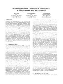
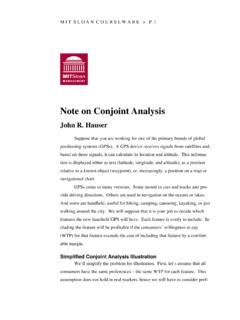
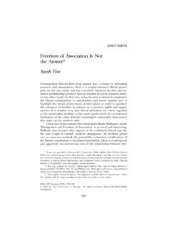
1 Analog-to-DigitalConverterTestingKent essential buildingblocks in criticallinkbetween front-endanalogtransducersandback-enddig italcomputersthatcan e ciently implement a widevariety of of digital-signal-processingapplicationslea dsto the availability of a widevariety of Analog-to-Digital (A/D)convertersof varyingprice,performance,and , an A/Dconverterencodes a continuous-timeanaloginputvoltage,VIN, into a seriesofdiscreteN-bit digitalwordsthatsatisfythe relationVIN=VFSN 1Xk=0bk2k+1+ whereVFSis the full-scalevoltage,bkare the individualoutputbits,and is the alsobe writtenin termsof the leastsigni cant bit (LSB)or quantumvoltagelevelVQ=VFS2N= 1 LSBasVIN=VQN 1Xk=0bk2k+ A plotof this idealcharacteristicfor a 3-bitA/Dconverteris shown in OutputAnalog Input1/801/43/81/25/83/47/8 FScentercode= 1 LSBcode widthFigure1: uniquedigitalcode correspondsto a smallrangeof LSBwide(the\code width")and is centeredaroundthe \code center.
2 "All inputvoltagesresolveto the digitalcode of the nearestcode center. Thedi erencebetween the analoginputvoltageandthe correspondingvoltageof the nearestcode center (thedi erencebetween the solidand dashedlinesin Figure1) is the A/Dconverterhas a nitenumber of outputbits,even an idealA/Dconverterproducessomequantizatio nerrorwithevery A/DConverterFiguresof MeritThenumber of outputbitsfroman analog-to-digitalconverterdo not fullyspecifyits di erfromidealbehaviorin many ,such as gainando set,are easyto quantify, the successof many signal-processingapplicationsdependson the dynamicbehaviorof the , the applicationdeterminesthe requirements, and A/Dconverterresolutionmay not be eithernecessaryor su cient to specifythe many cases,the quality of the A/Dconvertermust be testedfor thespeci of analog-to-digitalconverterapplicationsle adsto a largenumber of guresof meritfor guresof meritincludeaccuracy, resolution,dynamicrange,o set,gain.
3 Di erential nonlinearity, integralnonlinearity, signal-to-noiseratio,signal-to-noise-and -distortionratio,e ective number of bits,spurious-freedynamicrange,intermodu lationdistortion,totalharmonicdistortion ,e ective resolutionbandwidth,full-power bandwidth,full-linearbandwidth,apertured elay, aperturejitter,transient response,and cationscan be looselydividedinto threecategories| staticparameters,frequency-domaindynamic parameters,andtime-domaindynamicparamete rs| andare de nedin the A/Dconverterspeci cationsthatcan be testedat low speed,or evenwithconstant cationsincludeaccuracy, resolution,dynamicrange,o set,gain,di erential nonlinearity, and the totalerrorwithwhich the A/Dconvertercan convert a known voltage,includingthe e ectsof quantizationerror,gainerror,o seterror,and , accuracyshouldbe traceableto known standards(for example,NIST),and is generallya \catch-all"termfor all the number of bits,N, out of the Figure1shows a 3- mostnoticeablespeci cation,resolutiondeterminesthesize of the leastsigni cant bit, and thus determinesthe dynamicrange,the code widths,and the ratioof the smallestpossibleoutput(theleastsigni cant bit or quantumvoltage)to the largestpossibleoutput(full-scalevoltage)
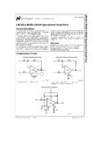
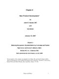
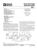
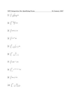
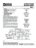
4 ,mathematically20 log102N setErrorO seterroris the deviationin the A/Dconverter'sbehaviorat rsttransitionvoltageshouldbe 1=2 LSBabove seterroris the deviationof the actualtransitionvoltagefromthe ideal1=2 seterroris easilytrimmedby locationof the rsttransitionsin Figures1 and OutputAnalog Input01/81/43/81/25/83/47/8 FSFigure2: Analog-to-digitalconvertercharacteristic ,showingo setand the deviationin the slope of the line throughthe A/Dconverter'send points at zeroand full scalefromthe idealslope of 2N=VFScodes-per-volt. Like o seterror,gainerroris easilycorrectedby slope of the dashedlinesin Figures1 and OutputAnalog Inputmaximum1/81/43/81/25/83/47/8 FSnarrow code widthsnegative DNLwide code widthspositive DNLmissing codeINL = 1 LSBF igure3: Analog-to-digitalconvertercharacteristic ,showingnonlinearity errorsand a is the idealcharacteristic,and the dottedline is the best erential NonlinearityDi erential nonlinearity (DNL)is the deviationof the code transitionwidthsfromthe idealwidthof 1 code widthsin the idealA/Dconverterare 1 LSBwide,so the DNLwouldbe onlythe \maximum DNL.
5 "See the widerangeof code widthsillustratedin (INL)is the distanceof the code centers in the A/Dconvertercharacteristicfromthe all code centerslandon the idealline,the INLis onlythe \maximum INL."See the deviationsof the code centers fromthe ideallinein two possibleways to expressmaximum INL,dependingon your de nitionof the \idealline."DatasheetINLnumbers can be decreasedby quotingmaximum INLfroma\best t" lineinsteadof the Figure3, the idealline(shown dashed)exhibitsanINLof 1 LSB,whilethe best- tline (shown dotted)exhibitsan INLof half e ectof INLon totalaccuracy, it is probablya betterre ectionof the A/Dconverter'slinearity in are outputdigitalcodes thatare not producedfor any inputvoltage,usuallydue someconverters,missingcodes can be causedby non-monotonicity of the Figure3 causescode 100 to be \crowdedout.
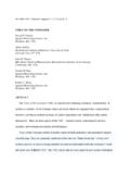
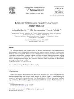
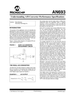
6 " QuantizationNoiseQuantizationerrordue to the niteresolutionNof the A/Dconverterlimitsthe in an idealA/Dconverter,the quantizationof the inputsignalcreateserrorsthatbehave like inputswithin 1=2 LSBof a code center resolve to thatdigitalcode. Thus,therewill be a smalldi erencebetween the code center and the actualinputvoltagedue to assumethatthis errorvoltageis uncorrelatedand distributeduniformly, we cancalculatethe expectedrms valueof this \quantizationnoise."11111010110001101000 1000 Digital OutputAnalog Input1/801/43/81/25/83/47/8 FScentercode= 1 LSBcode width01/81/43/81/25/83/47/8 FSAnalog InputError VoltageError = Output InputFigure4: Quantizationerrorvoltagefor to quantizationcan be the error5voltageis the quantumvoltagelevel (theleastsigni cant bit)VQ=VFS2N= 1 LSBF initeamplituderesolutionintroducesa quantizationerrorbetween the analoginputvoltageandthe quantizationerrorvoltageis uniformlydistributedover the code widthfrom 1=2 LSBto +1=2 LSB,the expectationvalueof the errorvoltageisEf 2g=1 VQZ+12VQ 12VQ 2d =1VQ" 33#+12VQ 12VQ=V2Q12 Thisquantizationnoiseis assumedto be ,themaximum signal-to-noiseratiofor a full-scaleinputcan be valueof a full-scalepeak-to-peak amplitudeVFisVrms=VFS2p2=2 NVQ2p2thus the signal-to-noiseratioisSNR= 20 log VrmspE( 2)!
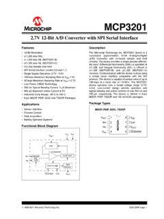
7 = 20 log(2Np1:5) = 6:02N+ 1:76 dBwhenthe noiseis due onlyto result,we can tabulatethe idealsignal-to-noiseratiofor several A/Dconverterresolutionsin : Idealsignal-to-noiseratiodue to shows the fast Fouriertransform(FFT)spectrumof a sinewave sampledby an ideal10- oor in this gureis dueonlyto anM-point FFT,the averagevalueof the noisecontainedin each frequencybin is 10 log2(M=2) dBbelow the rmsvalueof the \FFTprocessgain"is why the noise oorappears30 dB lower thanthe quantizationnoiselevel listedin realanalog-to-digitalconvertershave additionalnoisesourcesanddistortionproce ssesthatdegradethe performanceof the A/Dconverterfromthe the dynamicbehaviorof the A/Dconverterare quanti edand reportedina variety of amplitudeFFT frequency binFigure6: Quantizationnoise oor for an ideal10-bitA/Dconverter(4096point FFT).
8 (S/N+D,SINAD,or SNDR)is the ratioof the inputsignalamplitudeto the rms sumof all otherspectralcomponents. For anM-point FFTof a sinewavetest,if the fundamental is in frequencybinm(withamplitudeAm), the SNDRcan be calculatedfromthe FFTamplitudesSNDR= 10 log264A2m0@m 1Xk=1A2k+M=2Xk=m+1A2k1A 1375To avoid any spectralleakage aroundthe fundamental, oftenseveral binsaroundthe fundamentalare dependent on the input-signalfrequencyand amplitude,degradingathighfrequencyand power. Measuredresultsare oftenpresented in plotsof SNDR versusfrequencyfor a constant-amplitudeinput,or SNDR versusamplitudefor a ective Number of BitsE ective number of bits (ENOB)is simplythe signal-to-noise-and-distortionratioexpre ssedin bitsratherthandecibels by solvingthe \idealSNR"equationSNR= 6:02N+ 1:76 dBfor the number of bitsN, usingthe measuredSNDRENOB=SNDR 1:76 dB6:02 dB=bitIn the presentationof measuredresults,ENOBis identicalto SNDR,witha changein the scalingof the DynamicRangeSpurious-freedynamicrange(SF DR)is the ratioof the inputsignalto the peak spuriousor peakharmoniccomponent.
9 Spurscan be createdat harmonicsof the inputfrequencydue to nonlineari-ties in the A/Dconverter,or at subharmonicsof the samplingfrequencydue to mismatch or clock7couplingin the SFDRof an A/Dconvertercan be largerthanthe SFDRcan be facilitatedby increasingthe number of FFTpoints or by averagingseveral both cases,the noise oor will improve, whilethe amplitudeof the spurswill stay an A/Dconverterwithsigni cant harmonicspursis shown in Figure7. BecauseSFDRis oftenslew-ratedependent, it will be a functionof inputfrequencyand magnitude[1]. Themaximum SFDR oftenoccursat an amplitudebelow full amplitudeFFT frequency binFigure7: A/Dconverterwithsigni cant nonlinearity, showingpoor the inputsignalare aliaseddown to frequenciesbelow the HarmonicDistortionTotal harmonicdistortion(THD)is the ratioof the rms sumof the rst ve harmoniccomponents(or theiraliasedversions,as in Figure7) to the inputsignalTHD= 10 log V22+V23+V24+V25+V26V21!
10 WhereV1is the amplitudeof the fundamental, andVnis the amplitudeof then-th (IMD)is the ratioof the amplitudesof the sumand di erencefrequenciesto the inputsignalsfor a two-tonetest,sometimesexpressedas \intermod-freedynamicrange(IFDR)"See the FFTspectrumin Figure8. For second-orderdistortion,the IMDwouldbeIMD= 10 log V2++V2 V21+V22!whereV1andV2are the rms amplitudesof the inputsignals,andV+andV are the rms amplitudesof the sumand di ective ResolutionBandwidthE ective resolutionbandwidth(ERBW)is the input-signalfrequencywherethe SNDRof the A/Dconverterhas fallenby 3 dB ( ) fromits valuefor amplitudeFFT frequency binFigure8: Two-toneIMDtest withsecond-ordernonlinearity, showing(fromleft)F2 F1product,F1input,F2input,2F1product,F1+ F2product,and BandwidthIn ampli ers,full-power bandwidth(FPBW)is the maximum frequencyat which the ampli ercan reproducea full-scalesinusoidaloutputwithoutdistort ion(sometimescalculatedas slew-ratedividedby 2 Vmax), or wherethe amplitudeof full-scalesinusoidis reducedby 3 dB.