Transcription of AND9093 - Using MOSFETs in Load Switch Applications
1 AND9093 /D. Using MOSFETs in load Switch Applications APPLICATION NOTE. Introduction In today's market, power management is more important for the same die area. Thus, for high current Applications the than ever. Portable systems strive to extend battery life while N-channel transistor is preferred. meeting an ever increasing demand for higher performance. When Using an N-channel MOSFET in a load Switch load switches provide a simple and inexpensive method for circuit, the drain is connected directly to the input voltage the system to make the appropriate power management rail and the source is connected to the load . The output decisions based on which peripherals or sub-circuits are voltage is defined as the voltage across the load , and currently in use. load switches are found in notebooks, cell therefore: phones, hand held gaming systems and many other portable V S + V OUT (eq.)
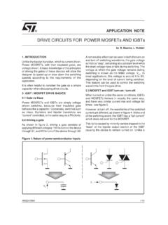
2 1). devices. The load Switch is controlled by the system, and connects In order for the N-channel MOSFET to turn on, the or disconnects a voltage rail to a specific load . By turning gate-to-source voltage must be greater than the threshold unused circuitry off, the system as a whole can run more voltage of the device. This means that: efficiently. The load Switch provides a simple means to V G w V OUT ) V th (eq. 2). power a load when it is in demand and allows the system to In order to meet Equation 2, a second voltage rail is maximize performance. needed to control the gate. Therefore, the input voltage rail can be considered independently of the pass transistor. load Switch Basics A load Switch is comprised of two main elements: the pass Because of this, the N-channel load Switch can be used for transistor and the on/off control block, as shown in Figure 1.
3 Very low input voltage rails or for higher voltage rails, as long as the gate-to-source voltage VGS remains higher than P-channel the threshold voltage of the device. The designer must load Switch ensure that the device maximum ratings and the safe operating area of the MOSFET are not violated. + When Using a P-channel MOSFET in a load Switch circuit VIN load (as in Figure 1, the source is directly connected to the input . On/Off voltage rail and the drain is connected to the load . In order Control for the P-channel load Switch to turn on, the source-to-gate voltage must be greater than the threshold voltage. Therefore: Figure 1. Example load Switch Circuit V IN w V G ) V th (eq. 3). The pass transistor is most commonly a MOSFET (either At minimum, the input voltage rail must be greater than N-channel or P-channel) that passes the voltage supply to the threshold voltage of the selected pass transistor a specified load when the transistor is on.
4 (assuming the gate voltage is 0 V when the load Switch is turned on). N-channel and P-channel Considerations The selection of a P-channel or N-channel load Switch The P-channel MOSFET has a distinct advantage over the depends on the specific needs of the application. The N-channel MOSFET, and that is in the simplicity of the N-channel MOSFET has several advantages over the on/off control block. The N-channel load Switch requires an P-channel MOSFET. For example, the N-channel majority additional voltage rail for the gate; the P-channel load Switch carriers (electrons) have a higher mobility than the does not. As with the N-channel MOSFET, the designer P-channel majority carriers (holes). Because of this, the must ensure that the device maximum ratings and the safe N-channel transistor has lower RDS(on) and gate capacitance operating area of the P-channel MOSFET are not violated.
5 Semiconductor Components Industries, LLC, 2014 1 Publication Order Number: February, 2014 Rev. 1 AND9093 /D. AND9093 /D. load Switch Control Circuit Considerations source. As with the N-channel control circuit, resistor R1 is There are multiple ways to implement the on/off control selected so that milliamps of current or less flow through R1. block in a load Switch circuit. This section will cover one when Q1 is on. A standard range is 1 kW 10 kW. control circuit example for the N-channel and one for the For both control circuit implementations, the small-signal P-channel load Switch . NMOS transistor, Q1, can be integrated into the same N-channel package as the pass transistor. load Switch VOUT. Efficiency Considerations Efficiency is critical to the success of the overall power + load management of the system.
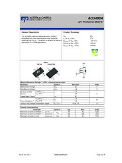
6 In a load Switch circuit, the load VIN R1. current flows directly through the pass transistor when it is + turned on. Therefore, the main power loss is the conduction VGATE loss.. Q1 P LOSS + I load 2 @ R DS(on) (eq. 4). EN. The RDS(ON) of the pass transistor causes a voltage drop between the input voltage and the output voltage, as shown in Equation 5. For Applications requiring high load currents Figure 2. N-channel Example Control Circuit or low voltage rails, this voltage drop becomes critical. The Figure 2 shows an example load Switch control circuit for voltage drop will increase as the load current increases, and an N-channel pass transistor. A logic signal from the system the voltage drop at maximum load must be taken into power management control circuitry turns the load Switch consideration when selecting the pass transistor.
7 On and off via a small-signal NMOS transistor, Q1. When V OUT + V IN * I load @ R DS(on) (eq. 5). EN is LOW, Q1 is off and the pass transistor gate is pulled As discussed in previous sections, the N-channel up to VGATE to keep it turned on. When EN is HIGH, Q1. MOSFET has an RDS(on) advantage over the P-channel turns on, the pass transistor gate is pulled to ground, and the MOSFET for a given die size. The RDS(on) of an N-channel load Switch turns off. Resistor R1 is selected so that device can be two times lower than the RDS(on) of milliamps of current or less flow through R1 when Q1 is on. a P-channel device of similar die area. This difference is A standard range is 1 kW 10 kW. most prominent at higher currents, but the N-channel An additional voltage source, VGATE, is needed to keep RDS(on) advantage becomes less prominent at lower the gate-to-source forward biased.
8 As expressed in currents. For Applications such as cell phones and other Equation 2, the gate voltage must be larger than the sum of portable low power devices, higher efficiency can be the output voltage and the threshold voltage. This may be attained Using a P-channel pass transistor, with the undesirable for systems that do not have an extra voltage rail advantage of a simpler control circuit. available. To illustrate this, let's assume that a 30 mW N-channel P-channel transistor and a 50 mW P-channel transistor have similar die load Switch VOUT size. The efficiency impact of the two devices will be examined for a high current application and a low current R1. + application. load VIN For the first example, consider an application that requires . a maximum load current of 10 A. Using Equations 4 and 5, Q1.
9 EN the power loss at the maximum load is calculated to be 3 W. for the N-channel transistor, and the voltage drop across the transistor is 300 mV. The power loss at the maximum load is 5 W for the P-channel transistor, and the voltage drop Figure 3. P-channel Example Control Circuit across the transistor is 500 mV. Figure 3 shows an example load Switch control circuit for Now consider an application in which the maximum a P-channel pass transistor. As with the N-channel example, current is 2 A. The power loss at maximum load is 120 mW. a logic signal from the system power management control for the N-channel device and 200 mW for the p-channel circuitry turns the load Switch on and off via a small-signal device. The voltage drop for the N-channel transistor is NMOS transistor, Q1. When EN is LOW, Q1 is off and the 60 mV and is 100 mV for the P-channel transistor.
10 Gate is pulled up to VIN. When EN is HIGH, Q1 turns on, the As a final example, consider an application with an pass transistor gate is pulled to ground, and the load Switch 850 mA maximum load current. The 30 mW N-channel turns on. As long as the input voltage rail is higher than the transistor's power loss is mW compared to the threshold voltage of the PMOS transistor, it will turn on mW power loss of the 50 mW P-channel transistor of when EN is HIGH without the need of an additional voltage similar die size. For low current Applications , the N-channel 2. AND9093 /D. RDS(ON) advantage becomes negligible. P-channel pass P-channel transistors can be designed to have RDS(on) as low as 8 mW. load Switch VOUT. Low RDS(on) is critical for maximizing the efficiency of the VIN +. load R2 C1. load Switch circuit and minimizing the voltage drop across.