Transcription of LDO Regulator - Ultra-Low Noise, High PSRR, RF and Analog ...
1 NCP163. LDO Regulator - Ultra-Low Noise, High PSRR, RF and Analog Circuits 250 mA. The NCP163 is a next generation of high PSRR, ultra low noise LDO capable of supplying 250 mA output current. Designed to meet the requirements of RF and sensitive Analog circuits, the NCP163 MARKING. device provides ultra low noise, high PSRR and low quiescent DIAGRAMS. current. The device also offer excelent load/line transients. The NCP163 is designed to work with a 1 mF input and a 1 mF output WLCSP4. A1 X. ceramic capacitor. It is available in two thickness ultra small , CASE 567JZ. WLCSP Packages, XDFN4 and industry standard SOT23 5L. Features WLCSP4 X. A1. Operating Input Voltage Range: V to V CASE 567KA. Available in Fixed Voltage Option: V to V. 2% Accuracy Over Load/Temperature XDFN4. XX M. ultra Low Quiescent Current Typ.
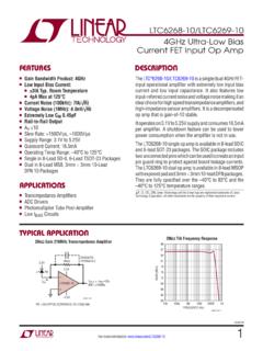
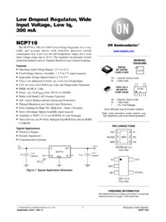
2 12 mA 1. CASE 711AJ. 1. Standby Current: Typ. mA. Very Low Dropout: 80 mV at 250 mA. SOT23 5L. ultra High PSRR: Typ. 92 dB at 20 mA, f = 1 kHz CASE 527AH. XXX MG. G. ultra Low Noise: mVRMS. Stable with a 1 mF Small Case Size Ceramic Capacitors Available in WLCSP4: mm x mm x mm X, XXX = Specific Device Code M = Date Code WLCSP4: mm x mm x mm G = Pb Free Package XDFN4: 1 mm x 1 mm x mm (Note: Microdot may be in either location). SOT23 5: mm x mm x mm These Devices are Pb Free, Halogen Free/BFR Free and are RoHS PIN CONNECTIONS. Compliant IN OUT. Typical Applications Battery powered Equipment A1 A2. Wireless LAN Devices Smartphones, Tablets B1 B2. Cameras, DVRs, STB and Camcorders EN GND. (Top View) (Top View). VIN VOUT. IN OUT. NCP163 IN 1 5 OUT. CIN EN COUT. 1 mF ON 1 mF GND 2. Ceramic Ceramic OFF GND.
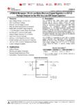
3 EN 3 4 NC. (Top View). Figure 1. Typical Application Schematics ORDERING INFORMATION. See detailed ordering, marking and shipping information on page 17 of this data sheet. Semiconductor Components Industries, LLC, 2016 1 Publication Order Number: September, 2019 Rev. 9 NCP163/D. NCP163. IN. ENABLE THERMAL. EN LOGIC SHUTDOWN. BANDGAP. REFERENCE MOSFET. INTEGRATED. DRIVER WITH. SOFT START. CURRENT LIMIT. OUT. * ACTIVE DISCHARGE. Version A only EN. GND. Figure 2. Simplified Schematic Block Diagram PIN FUNCTION DESCRIPTION. Pin No. Pin No. Pin No. Pin WLCSP4 SOT23 5L XDFN4 Name Description A1 1 4 IN Input voltage supply pin A2 5 1 OUT Regulated output voltage. The output should be bypassed with small 1 mF ceramic capacitor. B1 3 3 EN Chip enable: Applying VEN < V disables the Regulator , Pulling VEN > V.
4 Enables the LDO. B2 2 2 GND Common ground connection 4 NC Not connected. Can be tied to ground plane. EPAD EPAD Exposed pad. Can be tied to ground plane for better power dissipation. ABSOLUTE MAXIMUM RATINGS. Rating Symbol Value Unit Input Voltage (Note 1) VIN V to 6 V. Output Voltage VOUT to VIN + , max. 6 V V. Chip Enable Input VCE to 6 V V. Output Short Circuit Duration tSC unlimited s Maximum Junction Temperature TJ 150 C. Storage Temperature TSTG 55 to 150 C. ESD Capability, Human Body Model (Note 2) ESDHBM 2000 V. ESD Capability, Machine Model (Note 2) ESDMM 200 V. ESD Capability, Charged Device Model (Note 2) ESDCDM 1000 V. Stresses exceeding those listed in the Maximum Ratings table may damage the device. If any of these limits are exceeded, device functionality should not be assumed, damage may occur and reliability may be affected.
5 1. Refer to ELECTRICAL CHARACTERISTICS and APPLICATION INFORMATION for Safe Operating Area. 2. This device series incorporates ESD protection and is tested by the following methods: ESD Human Body Model tested per EIA/JESD22 A114. ESD Machine Model tested per EIA/JESD22 A115. ESD Charged Device Model tested per EIA/JESD22 C101, Field Induced Charge Model Latchup Current Maximum Rating tested per JEDEC standard: JESD78. 2. NCP163. THERMAL CHARACTERISTICS. Rating Symbol Value Unit Thermal Characteristics, WLCSP4 (Note 3), Thermal Resistance, Junction to Air 108. Thermal Characteristics, XDFN4 (Note 3), Thermal Resistance, Junction to Air RqJA C/W. Thermal Characteristics, SOT23 5 (Note 3), Thermal Resistance, Junction to Air 218. 3. Measured according to JEDEC board specification. Detailed description of the board can be found in JESD51 7.
6 ELECTRICAL CHARACTERISTICS 40 C TJ 125 C; VIN = VOUT(NOM) + 1 V; IOUT = 1 mA, CIN = COUT = 1 mF, unless otherwise noted. VEN = V. Typical values are at TJ = +25 C (Note 4). Parameter Test Conditions Symbol Min Typ Max Unit Operating Input Voltage VIN V. Output Voltage Accuracy VIN = (VOUT(NOM) + 1 V) to V. 2 +2. 0 mA IOUT 250 mA. VIN = (VOUT(NOM) + 1 V) to V. 0 mA IOUT 250 mA VOUT 3 +3 %. (for VOUT < V, XDFN4 package). VIN = (VOUT(NOM) + 1 V) to V. 2 +2. SOT23 5L Package Only Line Regulation VOUT(NOM) + 1 V VIN V LineReg %/V. Load Regulation WLCSP, XDFN4 IOUT = 1mA to 250mA LoadReg %/mA. SOT23 5L VOUT(NOM) = V 180 250. VOUT(NOM) = V 110 175. VOUT(NOM) = V 95 160. VOUT(NOM) = V 90 155. IOUT = 250 mA. Dropout Voltage (Note 5) (WLCSP, XDFN4 VOUT(NOM) = V VDO 85 149 mV. Packages). VOUT(NOM) = V 80 145.
7 VOUT(NOM) = V 75 140. VOUT(NOM) = V 65 120. VOUT(NOM) = V 75 105. VOUT(NOM) = V 205 280. IOUT = 250 mA VOUT(NOM) = V 120 190. Dropout Voltage (Note 5) (SOT23 5L VDO mV. Package) VOUT(NOM) = V 115 185. VOUT(NOM) = V 105 175. Output Current Limit VOUT = 90% VOUT(NOM) ICL 250 700. mA. Short Circuit Current VOUT = 0 V ISC 690. Quiescent Current IOUT = 0 mA IQ 12 20 mA. Shutdown Current VEN V, VIN = V IDIS 1 mA. EN Pin Threshold Voltage EN Input Voltage H VENH V. EN Input Voltage L VENL EN Pull Down Current VEN = V IEN mA. Turn On Time COUT = 1 mF, From assertion of VEN to 120 ms VOUT = 95% VOUT(NOM). Power Supply Rejection Ratio IOUT = 20 mA f = 100 Hz 91. f = 1 kHz 92. PSRR dB. f = 10 kHz 85. f = 100 kHz 60. 3. NCP163. ELECTRICAL CHARACTERISTICS 40 C TJ 125 C; VIN = VOUT(NOM) + 1 V; IOUT = 1 mA, CIN = COUT = 1 mF, unless otherwise noted.
8 VEN = V. Typical values are at TJ = +25 C (Note 4). Parameter Test Conditions Symbol Min Typ Max Unit Output Voltage Noise f = 10 Hz to 100 kHz IOUT = 1 mA VN mVRMS. IOUT = 250 mA Thermal Shutdown Threshold Temperature rising TSDH 160 C. Temperature falling TSDL 140 C. Active Output Discharge Resistance VEN < V, Version A only RDIS 280 W. Line Transient (Note 6) VIN = (VOUT(NOM) + 1 V) to (VOUT(NOM) +. 1. V) in 30 ms, IOUT = 1 mA. TranLINE mV. VIN = (VOUT(NOM) + V) to (VOUT(NOM) +. +1. 1 V) in 30 ms, IOUT = 1 mA. Load Transient (Note 6) IOUT = 1 mA to 200 mA in 10 ms 40. TranLOAD mV. IOUT = 200 mA to 1mA in 10 ms +40. Product parametric performance is indicated in the Electrical Characteristics for the listed test conditions, unless otherwise noted. Product performance may not be indicated by the Electrical Characteristics if operated under different conditions.
9 4. Performance guaranteed over the indicated operating temperature range by design and/or characterization. Production tested at TA = 25 C. Low duty cycle pulse techniques are used during the testing to maintain the junction temperature as close to ambient as possible. 5. Dropout voltage is characterized when VOUT falls 100 mV below VOUT(NOM). 6. Guaranteed by design. 4. NCP163. TYPICAL CHARACTERISTICS. VOUT, OUTPUT VOLTAGE (V). VOUT, OUTPUT VOLTAGE (V). IOUT = 10 mA. IOUT = 10 mA. IOUT = 250 mA. IOUT = 250 mA. VIN = V VIN = V. VOUT = V VOUT = V. CIN = 1 mF CIN = 1 mF. COUT = 1 mF COUT = 1 mF. 40 20 0 20 40 60 80 100 120 140 40 20 0 20 40 60 80 100 120 140. TJ, JUNCTION TEMPERATURE ( C) TJ, JUNCTION TEMPERATURE ( C). Figure 3. Output Voltage vs. Temperature Figure 4. Output Voltage vs. Temperature.
10 VOUT = V XDFN Package VOUT = V XDFN Package REGLINE, LINE REGULATION (%/V). VOUT, OUTPUT VOLTAGE (V). IOUT = 10 mA 0. IOUT = 250 mA VIN = V VIN = V. VOUT = V VOUT = V. CIN = 1 mF CIN = 1 mF. COUT = 1 mF. COUT = 1 mF. 40 20 0 20 40 60 80 100 120 140 40 20 0 20 40 60 80 100 120 140. TJ, JUNCTION TEMPERATURE ( C) TJ, JUNCTION TEMPERATURE ( C). Figure 5. Output Voltage vs. Temperature Figure 6. Line Regulation vs. Temperature . VOUT = V XDFN Package VOUT = V. 20. REGLOAD, LOAD REGULATION (mV). REGLINE, LINE REGULATION (%/V). 18 VIN = V. VOUT = V. 16. CIN = 1 mF. 14 COUT = 1 mF. 12. 0 10. 8. 6. VIN = V. VOUT = V 4. CIN = 1 mF 2. COUT = 1 mF. 0. 40 20 0 20 40 60 80 100 120 140 40 20 0 20 40 60 80 100 120 140. TJ, JUNCTION TEMPERATURE ( C) TJ, JUNCTION TEMPERATURE ( C). Figure 7. Line Regulation vs. Temperature Figure 8.