Transcription of MC33033 - Brushless DC Motor Controller
1 Semiconductor Components Industries, LLC, 2013 February, 2013 Rev. 111 Publication Order Number: MC33033 /DMC33033, NCV33033 Brushless DC Motor ControllerThe MC33033 is a high performance second generation, limitedfeature, monolithic Brushless dc Motor Controller which has evolvedfrom ON Semiconductor s full featured MC33034 and MC33035controllers. It contains all of the active functions required for theimplementation of open loop, three or four phase Motor control. Thedevice consists of a rotor position decoder for proper commutationsequencing, temperature compensated reference capable of supplyingsensor power, frequency programmable sawtooth oscillator, fullyaccessible error amplifier, pulse width modulator comparator, threeopen collector top drivers, and three high current totem pole bottomdrivers ideally suited for driving power MOSFETs.
2 Unlike itspredecessors, it does not feature separate drive circuit supply andground pins, brake input, or fault output in the MC33033 are protective features consisting ofundervoltage lockout, cycle by cycle current limiting with aselectable time delayed latched shutdown mode, and internal Motor control functions include open loop speed, forward orreverse direction, and run enable. The MC33033 is designed to operatebrushless motors with electrical sensor phasings of 60 /300 or120 /240 , and can also efficiently control brush dc 10 to 30 V Operation Undervoltage Lockout V Reference Capable of Supplying Sensor Power Fully Accessible Error Amplifier for Closed Loop ServoApplications High Current Drivers Can Control External 3 Phase MOSFETB ridge Cycle By Cycle Current Limiting Internal Thermal Shutdown Selectable 60 /300 or 120 /240 Sensor Phasings Also Efficiently Control Brush DC Motors with External MOSFETH Bridge NCV Prefix for Automotive and Other Applications RequiringUnique Site and Control Change Requirements.
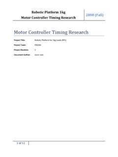
3 AEC Q100 Qualified and PPAP Capable Pb Free Packages are AvailableSO 20 LDW SUFFIXCASE 751 DPIN CONNECTIONSPDIP 20P SUFFIXCASE 738 ATBTTop DriveOutput12 BottomDrive Outputs11(Top View)13141516171098765 SensorInputs4 Error AmpInverting InputError AmpNon Inverting InputOscillatorReference OutputSCSBSA60 /120 SelectFwd/RevError Amp Out/PWM InputCurrent SenseNon Inverting InputGndCT1819 BBCB320 Output Enable2AB1 VCC201201 detailed ordering and shipping information in the packagedimensions section on page 25 of this data INFORMATIONSee general marking information in the device markingsection on page 25 of this data MARKING INFORMATIONMC33033, NCV33033 AmpPWMT hermalShutdownReferenceRegulatorLockoutU ndervoltageVCCFWR/REVQRSF asterSSVMS peedSetThis device contains 266 active 1.
4 Representative Schematic DiagramRotorPositionDecoderOutput BuffersCurrent Sense60 /120 NNMC33033, NCV33033 RATINGSR atingSymbolValueUnitPower Supply VoltageVCC30 VDigital Inputs (Pins 3, 4, 5, 6, 18, 19) VrefVOscillator Input Current (Source or Sink)IOSC30mAError Amp Input Voltage Range(Pins 9, 10, Note 1)VIR to VrefVError Amp Output Current(Source or Sink, Note 2)IOut10mACurrent Sense Input Voltage RangeVSense to Drive Voltage (Pins 1, 2, 20)VCE(top)40 VTop Drive Sink Current (Pins 1, 2, 20)ISink(top)50mABottom Drive Output Current(Source or Sink, Pins 15,16, 17)IDRV100mAElectrostatic Discharge Sensitivity (ESD)Human Body Model (HBM) Class 2, JESD22 A114 CMachine Model (MM) Class A, JESD22 A115 ACharged Device Model (CDM), JESD22 C101 C 20002002000 VVVP ower Dissipation and Thermal CharacteristicsP Suffix, Dual In Line, Case 738 Maximum Power Dissipation @ TA = 85 CThermal Resistance, Junction to AirDW Suffix, Surface Mount, Case 751 DMaximum Power Dissipation @ TA = 85 CThermal Resistance, Junction to AirPDR JAPDR JA86775619105mW C/WmW C/WOperating Junction TemperatureTJ150 COperating Ambient Temperature Range (Note 3) MC33033 NCV33033TA 40 to + 85 40 to +125 CStorage Temperature RangeTstg 65 to +150 CStresses exceeding Maximum Ratings may damage the device.
5 Maximum Ratings are stress ratings only. Functional operation above theRecommended Operating Conditions is not implied. Extended exposure to stresses above the Recommended Operating Conditions may affectdevice The input common mode voltage or input signal voltage should not be allowed to go negative by more than The compliance voltage must not exceed the range of to NCV33033: Tlow = 40 C, Thigh = 125 C. Guaranteed by design. NCV prefix is for automotive and other applications requiring site and , NCV33033 CHARACTERISTICS (VCC = 20 V, RT = k, CT = 10 nF, TA = 25 C, unless otherwise noted.)CharacteristicSymbolMinTypMaxUnit REFERENCE SECTIONR eference Output Voltage (Iref = mA)TA = 25 C (Note 4) Regulation (VCC = 10 V to 30 V, Iref = mA)Regline Regulation (Iref = mA to 20 mA)Regload 1630mVOutput Short Circuit Current (Note 5)ISC4075 mAReference Under Voltage Lockout AMPLIFIERI nput Offset Voltage (Note 4)VIO Offset Current (Note 4)IIO Bias Current (Note 4)IIB 46 1000nAInput Common Mode Voltage RangeVICR(0 V to Vref)VOpen Loop Voltage Gain (VO = V, RL = 15 k)AVOL7080 dBInput Common Mode Rejection RatioCMRR5586 dBPower Supply Rejection Ratio (VCC = 10 V to 30 V)PSRR65105 dBOutput Voltage SwingHigh State (RL = 15 k to Gnd)Low State (RL = 17 k to Vref)
6 MC33033 : TA = 40 C to + 85 C; NCV33033: TA = 40 C to +125 Maximum package power dissipation limits must be , NCV33033 CHARACTERISTICS (continued) (VCC = 20 V, RT = k, CT = 10 nF, TA = 25 C, unless otherwise noted.)CharacteristicSymbolMinTypMaxUnit OSCILLATOR SECTIONO scillator FrequencyfOSC222528kHzFrequency Change with Voltage (VCC = 10 V to 30 V) fOSC/ V Peak VoltageVOSC(P) Valley VoltageVOSC(V) VLOGIC INPUTSI nput Threshold Voltage (Pins 3, 4, 5, 6, 18, 19)High StateLow Inputs (Pins 4, 5, 6)High State Input Current (VIH = V)Low State Input Current (VIL = 0 V)IIHIIL 150 600 70 337 20 150 AForward/Reverse, 60 /120 Select and Output Enable(Pins 3, 18, 19)High State Input Current (VIH = V)Low State Input Current (VIL = 0 V)
7 IIHIIL 75 300 36 175 10 75 ACURRENT LIMIT COMPARATORT hreshold VoltageVth85101115mVInput Common Mode Voltage RangeVICR VInput Bias CurrentIIB AOUTPUTS AND POWER SECTIONSTop Drive Output Sink Saturation (ISink = 25 mA)VCE(sat) Drive Output Off State Leakage (VCE = 30 V)IDRV(leak) ATop Drive Output Switching Time (CL = 47 pF, RL = k)Rise TimeFall Timetrtf 10726300300nsBottom Drive Output VoltageHigh State (VCC = 30 V, Isource = 50 mA)Low State (VCC = 30 V, Isink = 50 mA)VOHVOL(VCC ) (VCC ) Drive Output Switching Time (CL = 1000 pF)Rise TimeFall Timetrtf 3830200200nsUnder Voltage LockoutDrive Output Enabled (VCC Increasing)HysteresisVth(on) Supply CurrentICC 1522mAMC33033, NCV33033 , OUTPUT VOLTAGE (V)VO, OUTPUT VOLTAGE (V) s/DIVAV = + LoadTA = 25 s/DIVAV = + LoadTA = 25 , OUTPUT LOAD CURRENT (mA)f, FREQUENCY (Hz) k2202001801601401201008060-24-16- M100 k10 k40240 AVOL, OPEN-LOOP VOLTAGE GAIN (dB)EXCESS PHASE (DEGREES), PhaseGainTA, AMBIENT TEMPERATURE ( C)-55- OSCOSCILLATOR FREQUENCY CHANGE (%), , TIMING RESISTOR (k ) OSCOSCILLATOR FREQUENCY (kHz),Figure 2.
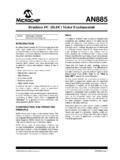
8 Oscillator Frequency versusTiming ResistorFigure 3. Oscillator Frequency Change versus TemperatureFigure 4. Error Amp Open Loop Gain andPhase versus FrequencyFigure 5. Error Amp Output Saturation Voltage versus Load CurrentFigure 6. Error Amp Small Signal Transient ResponseFigure 7. Error Amp Large Signal Transient , OUTPUT SATURATION VOLTAGE (V)VCC = 20 VTA = 25 CVCC = 20 VRT = kCT = 10 nFSource Saturation(Load to Ground)VCC = 20 VTA = 25 CVCC = 20 VVO = VRL = 15 kCL = 100 pFTA = 25 CSink Saturation(Load to Vref)CT = nFCT = 10 nFCT = 100 nFMC33033, NCV33033 , OUTPUT SATURATION VOLTAGE (V)Vsat0 ISink, SINK CURRENT (mA) , AMBIENT TEMPERATURE ( C)-25-40-20-5504020125100755025 NORMALIZED REFERENCE VOLTAGE CHANGE (mV) Vref,0 Iref, REFERENCE OUTPUT SOURCE CURRENT (mA)0605040302010-24-20- 12- 16 Vref,REFERENCE OUTPUT VOLTAGE CHANGE (mV) Figure 8.
9 Reference Output Voltage Changeversus Output Source CurrentFigure 9. Reference Output Voltage versus Supply VoltageFigure 10. Reference Output Voltage versus TemperatureFigure 11. Output Duty Cycle versus PWM Input VoltageFigure 12. Bottom Drive Response Time versusCurrent Sense Input VoltageFigure 13. Top Drive Output Saturation Voltageversus Sink , SUPPLY VOLTAGE (V) ,REFERENCE OUTPUT VOLTAGE (V) INPUT VOLTAGE (V)OUTPUT DUTY CYCLE (%)0 VSense, CURRENT SENSE INPUT VOLTAGE (NORMALIZED TO Vth) , BOTTOM DRIVE RESPONSE TIME (ns)No LoadTA = 25 CVCC = 20 VTA = 25 CVCC = 20 VRL = 1CL = nFTA = 25 CVCC = 20 VRT = kCT = 10 nFTA = 25 CVCC = 20 VNo LoadVCC = 20 VTA = 25 , NCV33033 , OUTPUT LOAD CURRENT (mA) , OUTPUT SATURATION VOLTAGE (V)sat50 ns/DIVVCC = 20 VCL = 15 pFTA = 25 C50 ns/DIVVCC = 20 VCL = nFTA = 25 C50 ns/DIVVCC = 20 VRL = kCL = 15 pFTA = 25 CFigure 14.
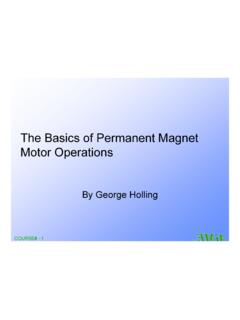
10 Top Drive Output WaveformFigure 15. Bottom Drive Output WaveformFigure 16. Bottom Drive Output WaveformFigure 17. Bottom Drive Output Saturation Voltage versus Load CurrentFigure 18. Supply Current versus VoltageVCC, SUPPLY VOLTAGE (V) , POWER SUPPLY CURRENT (mA)Sink Saturation(Load to VCC)Source Saturation(Load to Ground)VCC = 20 VTA = 25 CRT = kCT = 10 nFPins 3-6, 12, 13 = GndPins 18, 19 = OpenTA = 25 CVOUTPUT VOLTAGE (%)IOUTPUT VOLTAGE (%)OUTPUT VOLTAGE (%)010001000100MC33033, NCV33033 FUNCTION DESCRIPTION PinSymbolDescription1, 2, 20BT, AT, CTThese three open collector Top Drive Outputs are designed to drive the external upperpower switch Forward/Reverse Input is used to change the direction of Motor , 5, 6SA, SB, SCThese three Sensor Inputs control the commutation OutputThis output provides charging current for the oscillator timing capacitor CT and areference for the Error Amplifier.