Transcription of MC34063A - Inverting Regulator - Buck, Boost, Switching …
1 DATA Semiconductor Components Industries, LLC, 2016 August, 2021 Rev. 251 Publication Order Number: MC34063A /DInverting Regulator - Buck, boost , AMC34063A, MC33063A,SC34063A, SC33063A,NCV33063 AThe MC34063A Series is a monolithic control circuit containing theprimary functions required for DC to DC converters. These devicesconsist of an internal temperature compensated reference, comparator,controlled duty cycle oscillator with an active current limit circuit,driver and high current output switch. This series was specificallydesigned to be incorporated in Step Down and Step Up andVoltage Inverting applications with a minimum number of externalcomponents.
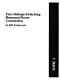
2 Refer to Application Notes AN920A/D and AN954/Dfor additional design Operation from V to 40 V Input Low Standby Current Current Limiting Output Switch Current to A Output voltage Adjustable Frequency Operation to 100 kHz Precision 2% Reference NCV Prefix for Automotive and Other applications RequiringUnique Site and Control Change Requirements; AEC Q100 Qualified and PPAP Capable These Devices are Pb Free, Halogen Free/BFR Free and are RoHSCompliantFigure 1. Representative Schematic DiagramSQRQ2Q1100 IpkOscillatorCTComparator+ VReferenceRegulator12345678 DriveCollectorIpkSenseVCCC omparatorInvertingInputSwitchCollectorSw itchEmitterTimingCapacitorGND(Bottom View)
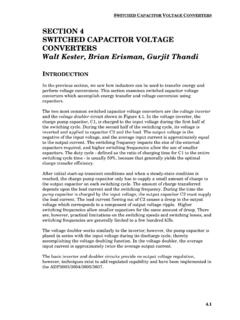
3 This device contains 79 active 8D SUFFIXCASE 751 PDIP 8P, P1 SUFFIXCASE 62618 See detailed ordering and shipping information in the packagedimensions section on page 12 of this data INFORMATIONx= 3 or 4A= Assembly LocationL, WL= Wafer LotY, YY= YearW, WW= Work WeekG or G= Pb Free Package183x063AP1 AWLYYWWG1833063 AVPAWLYYWWGMARKINGDIAGRAMS183x063 ALYWA G183x063 VALYWA G181 DFN8 CASE 488AF33063 ALYWAGMC34063A, MC33063A, SC34063A, SC33063A, SenseVCCC omparatorInvertingInput(Top View)2345678 Figure 2. Pin Connections (Top View)EP FlagSwitch CollectorSwitch EmitterTiming CapacitorGNDIpk SenseDriver CollectorComparator Inverting InputVCCMAXIMUM RATINGSR atingSymbolValueUnitPower Supply VoltageVCC40 VdcComparator Input voltage RangeVIR to + 40 VdcSwitch Collector VoltageVC(switch)40 VdcSwitch Emitter voltage (VPin 1 = 40 V)VE(switch)40 VdcSwitch Collector to Emitter VoltageVCE(switch)40 VdcDriver Collector VoltageVC(driver)40 VdcDriver Collector Current (Note 1)IC(driver)
4 100mASwitch Dissipation and Thermal CharacteristicsPlastic Package, P, P1 SuffixTA = 25 ResistanceRqJA115 C/WSOIC Package, D SuffixTA = 25 CPD625mWThermal ResistanceRqJA160 C/WThermal ResistanceRqJC45 C/WDFN PackageTA = 25 ResistanceRqJA80 C/WOperating Junction TemperatureTJ+150 COperating Ambient Temperature RangeTA CMC34063A, SC34063A0 to +70MC33063AV, NCV33063A 40 to +125MC33063A, SC33063A 40 to + 85 Storage Temperature RangeTstg 65 to +150 CStresses exceeding those listed in the Maximum Ratings table may damage the device. If any of these limits are exceeded, device functionalityshould not be assumed, damage may occur and reliability may be Maximum package power dissipation limits must be This device series contains ESD protection and exceeds the following tests: Human Body Model 4000 V per MIL STD 883, Method Model Method 400 NCV prefix is for automotive and other applications requiring site and change , MC33063A, SC34063A, SC33063A, CHARACTERISTICS (VCC = V, TA = Tlow to Thigh [Note 4], unless otherwise specified.)
5 CharacteristicsSymbolMinTypMaxUnitOSCILL ATORF requency (VPin 5 = 0 V, CT = nF, TA = 25 C)fosc243342kHzCharge Current (VCC = V to 40 V, TA = 25 C)Ichg243542mADischarge Current (VCC = V to 40 V, TA = 25 C)Idischg140220260mADischarge to Charge Current Ratio (Pin 7 to VCC, TA = 25 C) Current Limit Sense voltage (Ichg = Idischg, TA = 25 C)Vipk(sense)250300350mVOUTPUT SWITCH (Note 5)Saturation voltage , Darlington Connection(ISW = A, Pins 1, 8 connected)VCE(sat) voltage (Note 6)(ISW = A, RPin 8 = 82 W to VCC, Forced b ] 20)VCE(sat) Current Gain (ISW = A, VCE = V, TA = 25 C)hFE5075 Collector Off State Current (VCE = 40 V)IC(off) VoltageTA = 25 CTA = Tlow to voltage Line Regulation (VCC = V to 40 V)MC33063, MC34063MC33063V, NCV33063 Regline Bias Current (Vin = 0 V)IIB 20 400nATOTAL DEVICES upply Current (VCC = V to 40 V, CT = nF, Pin 7 = VCC,VPin 5 > Vth, Pin 2 = GND, remaining pins open)ICC parametric performance is indicated in the Electrical Characteristics for the listed test conditions, unless otherwise noted.
6 Productperformance may not be indicated by the Electrical Characteristics if operated under different Tlow = 0 C for MC34063, SC34063; 40 C for MC33063, SC33063, MC33063V, NCV33063 Thigh = +70 C for MC34063, SC34063; + 85 C for MC33063, SC33063; +125 C for MC33063V, NCV330635. Low duty cycle pulse techniques are used during test to maintain junction temperature as close to ambient temperature as If the output switch is driven into hard saturation (non Darlington configuration) at low switch currents ( 300 mA) and high driver currents( 30 mA), it may take up to ms for it to come out of saturation.
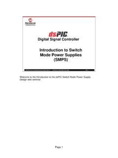
7 This condition will shorten the off time at frequencies 30 kHz, and ismagnified at high temperatures. This condition does not occur with a Darlington configuration, since the output switch cannot saturate. If anon Darlington configuration is used, the following output drive condition is recommended:Forcedbof output switch :ICoutputICdriver mA *w10* The 100 W resistor in the emitter of the driver device requires about mA before the output switch , MC33063A, SC34063A, SC33063A, 3. Oscillator FrequencyVCC = V, Pin 7 = VCCPin 5 = GND, TA = 25 CCt, TIMING CAPACITOR CAPACITANCE (nF)OFF TIME (ms)ON TIME (ms), FREQUENCY (kHz)ON TIME (ms)OFF TIME (ms)FREQUENCY (kHz)VCC = VPin 7 = VCCPin 2 = GNDPins 1, 5, 8 = OpenCT = nFTA = 25 CFigure 4.
8 Timing Capacitor Waveform10 ms/DIV, OSCILLATOR voltage (V)OSC200 mV/DIVVF igure 5. Emitter Follower Configuration OutputSaturation voltage versus Emitter CurrentFigure 6. Common Emitter Configuration OutputSwitch Saturation voltage versusCollector CurrentFigure 7. Current Limit Sense Voltageversus TemperatureFigure 8. Standby Supply Current versusSupply , SATURATION voltage (V)CE(sat)IE, EMITTER CURRENT (A)VVCC = V Pins 1, 7, 8 = VCCPins 3, 5 = GNDTA = 25 C(See Note 7), SATURATION voltage (V)CE(sat) , COLLECTOR CURRENT(A)VDarlington ConnectionForced b = 20-55-250255075100125, CURRENT LIMIT SENSE voltage (V)IPK(sense)TA, AMBIENT TEMPERATURE ( C)VVCC = VIchg = , SUPPLY CURRENT (mA)CCVCC, SUPPLY voltage (V)ICT = nF Pin 7 = VCCPin 2 = = V Pin 7 = VCCPins 2, 3, 5 = GNDTA = 25 C(See Note 7)7.
9 Low duty cycle pulse techniques are used during test to maintain junction temperature as close to ambient temperature as , MC33063A, SC34063A, SC33063A, V100+ kR247 kSQRQ2Q1 IpkOSCCTVCC+ VRefReg12341N5819CT1500pF330CO+Vout28 V/175 mH+100 Optional FilterTestConditionsResultsLine RegulationVin = V to 16 V, IO = 175 mA30 mV = RegulationVin = 12 V, IO = 75 mA to 175 mA10 mV = RippleVin = 12 V, IO = 175 mA400 mVppEfficiencyVin = 12 V, IO = 175 Ripple With Optional FilterVin = 12 V, IO = 175 mA40 mVppFigure 9. Step Up ConverterMC34063A, MC33063A, SC34063A, SC33063A, External NPN Switch9b.
10 External NPN Saturated Switch(See Note 8)876 RscVin12 VoutRR 0 for constant Vin8. If the output switch is driven into hard saturation (non Darlington configuration) at low switch currents ( 300 mA) and high driver currents( 30 mA), it may take up to ms to come out of saturation. This condition will shorten the off time at frequencies 30 kHz, and is magnifiedat high temperatures. This condition does not occur with a Darlington configuration, since the output switch cannot saturate. If anon Darlington configuration is used, the following output drive condition is 10.