Transcription of ON Semiconductor Is Now
1 To learn more about onsemi , please visit our website at SemiconductorIs Nowonsemi and and other names, marks, and brands are registered and/or common law trademarks of Semiconductor Components Industries, LLC dba onsemi or its affiliates and/or subsidiaries in the United States and/or other countries. onsemi owns the rights to a number of patents, trademarks, copyrights, trade secrets, and other intellectual property. A listing of onsemi product/patent coverage may be accessed at onsemi reserves the right to make changes at any time to any products or information herein, without notice. The information herein is provided as-is and onsemi makes no warranty, representation or guarantee regarding the accuracy of the information, product features, availability, functionality, or suitability of its products for any particular purpose, nor does onsemi assume any liability arising out of the application or use of any product or circuit, and specifically disclaims any and all liability, including without limitation special, consequential or incidental damages.
2 Buyer is responsible for its products and applications using onsemi products, including compliance with all laws, regulations and safety requirements or standards, regardless of any support or applications information provided by onsemi. Typical parameters which may be provided in onsemi data sheets and/or specifications can and do vary in different applications and actual performance may vary over time. All operating parameters, including Typicals must be validated for each customer application by customer s technical experts. onsemi does not convey any license under any of its intellectual property rights nor the rights of others. onsemi products are not designed, intended, or authorized for use as a critical component in life support systems or any FDA Class 3 medical devices or medical devices with a same or similar classification in a foreign jurisdiction or any devices intended for implantation in the human body.
3 Should Buyer purchase or use onsemi products for any such unintended or unauthorized application, Buyer shall indemnify and hold onsemi and its officers, employees, subsidiaries, affiliates, and distributors harmless against all claims, costs, damages, and expenses, and reasonable attorney fees arising out of, directly or indirectly, any claim of personal injury or death associated with such unintended or unauthorized use, even if such claim alleges that onsemi was negligent regarding the design or manufacture of the part. onsemi is an Equal Opportunity/Affirmative Action Employer. This literature is subject to all applicable copyright laws and is not for resale in any manner. Other names and brands may be claimed as the property of others. Semiconductor Components Industries, LLC, 2016 April, 2016 Rev.
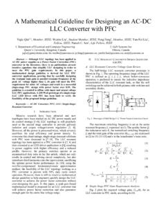
4 01 Publication Order Number:AND9408/DAND9408/DBasic Principles of LLCR esonant Half BridgeConverter and DC/DynamicCircuit SimulationExamplesIntroductionLLC resonant half bridge converters are widely used inconsumer electronics, like powering the display panel ofLCD TV. However, the operating principles of a LLCresonant half bridge converter are far from apparent andintuitive [1]. This application note focuses on the intuitiveand conceptual understanding of a llc resonant basic mathematical equations are also shown in thisapplication note for fundamental quantitative understandingof llc resonant half bridge key topics, including evolution of LLC resonanthalf bridge converter , basic analyzing method, DCcharacteristics, features of typical switching waveforms,soft switching feature, and CCM/DCM features arecovered in this application hands on understanding of the llc resonant halfbridge converter evaluation board provided byON Semiconductor , spice simulation circuits are providedfor transient simulation and DC of llc resonant Half bridge ConverterFigure 1 is a typical llc resonant converter .
5 Values ofmajor circuit components are also shown in 1. Transient Simulation Circuit of LLCR esonant Half Bridge ConverterLr = 29 uHCr = 22 nFLoadResonant Tank**Cout = 220 uFVin = 400 VQ1Q2D1D2T1Lm = 411 uH16 : 1 Node : VinNode : swNode : RT 1 Node : VpNode : Vs 1 Node : Vs 2 Node : VoutWhile the llc resonant half bridge converter iscomplicated, its intrinsic structure is very simple. It startsfrom a voltage divider and then adds isolation andrectification to output. With the half bridge input, the LLCresonant half bridge converter topology is evolution has the following procedures as shown inthe next three Voltage Divider and Voltage Divider withResonant TankFigure 2. A Voltage DividerX2 VoltagedividerX1 Figure 3. An AC Voltage Divider Formed by aResonant TankLrCrLoadResonant Tank~~X1X2As shown in Figure 2, a regular voltage divider converts ahigher voltage to a lower voltage.
6 The same effect can beachieved by a resonant tank and a load resistance [2], asshown in Figure 3. In Figure 3, the steady state output voltageis about the same as the input voltage when the circuitoperates at its resonant frequency. The output voltage is lessthan input voltage when circuit is not operating at its resonantfrequency. The voltage divider ratio is frequency Wave Input and Transformer Isolated OutputFigure 4. A DC/AC resonant ConverterLrCrLoadResonant TankX1X2 Figure 5. A DC/AC resonant converter withTransformer Isolated LoadLrCrLoadResonant NOTEAND9408 as shown in Figure 4, the input of a voltage divideris formed by square wave, rather than a single frequencysinusoidal input. At steady state, the high frequencyharmonic waveforms of square wave input are filtered by theresonant tank, which results in sinusoidal load current.
7 Thesinusoidal output current is then isolated from resonant tankby a transformer, which results in circuit shown in Figure Rectification and Soft Switching at InputFigure 6. A DC/DC resonant ConverterLrCrLoadResonant TankX1X2**T1**D1D2 CoutFigure 7. A DC/DC resonant converter with SoftZVS SwitchingLrCrLoadResonant TankX1X2**T1**D1D2 CoutLMTo obtain DC voltage, output current of Figure 5 isrectified and stabilized by a large capacitance, providing astable DC voltage and power on the load, as shown inFigure 6. When the circuit in Figure 6 operates at resonantfrequency, the input current and output current are exactlyin phase, which means that both high side and low sideswitches are switching with zero current. However, thisbenefit does not exist when the switching frequency isdeviates from resonant frequency.
8 To achieve soft switchingin the vicinity of the resonant frequency, a magnetizingcurrent is developed within the transformer. Thismagnetizing current the phase node to ground before the lowside turns on and raises the phase node to the input voltagebefore the high side turns on, creating ZVS while switchingon. By controlling the magnetizing current of transformer,the switching off loss of high side and low side can a voltage divider, the output voltage is less than theinput voltage. However, a llc resonant converter canoperates in a mode that increases rather than decreases thevoltage. On the condition that Lm participates in theresonant tank as a resonant inductor, the output voltage is thevoltage of resonant inductor, which could results in outputvoltage much higher than the input regular llc resonant half bridge converter works acombination mode of a voltage divider and amplifier ofresonant inductor voltage of the resonant the resonant frequency, impedance of resonant tank iszero, which means the input voltage is 100% applied on theload.
9 As frequency deviates from the resonant frequency, theimpedance of resonant tank is larger and larger, whichmeans the voltage on load is lower and lower. By varying theoperating frequency, the output power can be basic features of llc resonant half bridgeconverter include HS&LS are 50% duty cycle, frequencyvariation controls load current, CCM/DCM is defined byrectifier current, not inductor current, and magnetizingcurrent of transformer is the soft switching current for ZVSswitching of Q1 and Analysis MethodFundamental Harmonics Approximation [3]In application, llc resonant converter works around thefrequency of resonant tank (formed by Lr, Cr). Due to thenature of LC filter, only the fundamental frequency of theinput voltage can pass through the filter.
10 All the harmonicsare filtered by the resonant tank. Based on this fact, thetopology of llc resonant converter could be simplified tothe circuit shown in Figure 8. In Figure 8, Rac is thereflected load from secondary side of transformer to primaryside of transformer when only the fundamental harmonics +8p2 N2 RLOAD(eq. 1)Here, N is the transformer turn ratio of primary side andsecondary Operating Modes [4]Depending on whether transformer is driving power to theoutput or not, the circuit of Figure 8 has two operatingmodes. One mode is Rac=0, which means the magnetizinginductance is cut off from circuit. This interval happenswhen the transformer is driving power to the output,resulting in the primary side of the transformer beenclamped to a constant voltage (the output voltage reflectedto primary side of transformer).