Transcription of Polycom Installed Voice
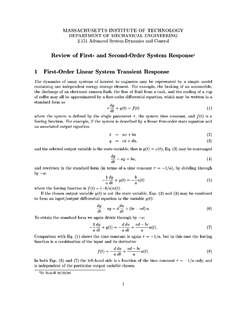
1 TM. Vortex / VSX 8000 Integration Application Note Polycom Installed Voice Business Group December 2004. 1. TABLE OF CONTENTS. INTRODUCTION ..4. CONNECTING THE VSX 8000 INPUTS AND OUTPUTS ..4. ENABLING THE VSX 8000 TO WORK WITH A VORTEX GAIN Microphone 7. Gain Structure for Line input 8. TESTING THE AUDIO INPUTS AND OUTPUTS ..8. CONTROLLING A VORTEX DEVICE VIA THE VSX 8000 ..8. 1.) Enable Vortex Mixer as an RS-232 Option in the VSX 9. 2.) Create the Appropriate Macros in the Vortex Device(s).. 10. Muting ..10. Volume Control (Codec Only)..12. Volume Control (Codec and Telephone)..15. 3.) Verify that the VSX 8000 Remote Control properly controls the Vortex 16. STANDARD AEC OPERATION ..17. Example .. 18. Introduction / Room System Conference Composer Matrix 21. Presets .. 22. STEREO AEC OPERATION ..24. Vortex Integration with the VSX 8000 Stereo 24.
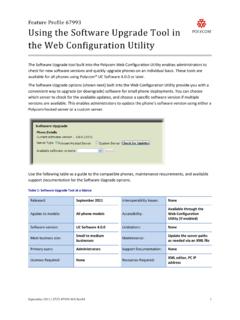
2 Example .. 26. Introduction / Room System Conference Composer Mic/Line 28. Matrix 28. Presets .. 30. 2. INTEGRATING A VSX 8000 / SOUNDSTATION VTX 1000 / AND A VORTEX DEVICE ..32. System Layout ..Error! Bookmark not defined. WIRING FROM VSX 8000 TO VORTEX DEVICE ..34. input to VSX 8000 from output of Vortex 34. output of VSX 8000 to input of Vortex 34. TIPS FOR VSX 8000 ..35. TECHNICAL SUPPORT ..36. Polycom Installed Voice Business Contact Information .. 36. 3. INTRODUCTION. This application note is designed to give instruction as to the setup and integration of the VSX . 8000 to a Vortex Device. CONNECTING THE VSX 8000 INPUTS AND OUTPUTS. In order to send and receive audio to the Polycom VSX 8000 codec, you need to connect the system as shown in Figure 1 and described below. 1. Connect one of the Outputs of the Vortex device to the mixer input of the codec.
3 By default, Outputs A, B, or C of the Vortex device are mix-minus versions of the Inputs A, B, or C signals, respectively. Any of these signals can be used with the default factory preset on the Vortex. If you are using Polycom InstantDesigner , choose the input and output that InstantDesigner recommends. 2. Connect the auxiliary line level output of the codec to one of the line level inputs of the Vortex device (Inputs A-D). If you have more line inputs, you may use one of the Mic/Line level inputs instead of a line level input , but you need to disable all processing on that Mic/Line input (AEC, AGC, NC, Automixer), disable Phantom Power, and set the input to line level versus the default of mic level. 3. Optionally connect the RS-232 interface between the VSX 8000 and the Vortex device. 4. Figure 1. Connecting the VSX 8000 to a Vortex EF2241.
4 5. You may use either the left or right channels for sending and receiving monaural audio to the VSX 8000. For stereo operation, both the left and right channels must be used. Please follow our instructions for wiring the Vortex device to the codec (See the section WIRING FROM VSX 8000 TO VORTEX DEVICE). Failure to do so may induce him and ground noise into the signals sent and received from the codec. ENABLING THE VSX 8000 TO WORK WITH A VORTEX. DEVICE. 1. Connect a video monitor to Video output 1 of the codec. 2. On the VSX 8000 User Interface, go to SYSTEM, ADMIN SETTINGS, AUDIO SETTINGS, and select NEXT for Page 2. Select the LINE input option for the input Type. Set the Level setting to 5. 3. (Optional) Enable the VSX 8000 to control the Vortex Device by setting Serial Port 1 or Serial Port 2 to Vortex Mixer. In the VSX 8000 User Interface, go to SYSTEM, ADMIN.
5 SETTINGS, GENERAL SETTINGS, SERIAL PORTS. For the appropriate port, select VORTEX MIXER for RS-232 Mode. Verify that the baud rate of the VSX 8000 matches the baud rate of the Vortex Device. See the page CONTROLLING A VORTEX DEVICE VIA THE VSX8000 for more information. 4. Once that is completed, make sure that the Codec input to the Vortex Device is assigned to the appropriate AEC Reference signal if the VSX 8000 will be used in Mono mode (Standard AEC Operation). If using InstantDesigner to create the configuration settings for the Vortex, the reference will be set automatically. For Stereo Mode, please refer to the STEREO AEC OPERATION section. 6. GAIN STRUCTURE. MICROPHONE LEVELS. For wired microphones, the input gain on the Vortex is dependent on the sensitivity of the microphone as well as the typical distance from the talker to the microphone.
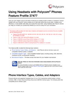
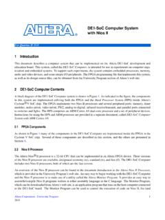
6 Table 1. Recommended microphone settings. Type of Microphone Average Level Tabletop Mic Mode, 15 dB. Ceiling Mic Mode, 25 dB. Podium Mic Mode, 10 dB. Gooseneck Mic Mode, 5 dB. Wireless Depends on the receiver*. *Some wireless receivers transmit audio at line level (approximately 0 to -10 dB) and others transmit at mic level (approximately -30 dB). Based on the transmit level, you may need to apply gain in the Vortex Device. For example, if a wireless receiver's nominal transmit level is -10 dB, you will need to apply +10 dB on the input of the Vortex Device to achieve unity (0 dB) gain. In order to set the gain appropriately, we recommend leaving all processing enabled and having someone talk into the microphone. Have another person watch the levels in Conference Composer or via the front panel of the Vortex device.
7 You want the speech to light up the first yellow LED (0 dBu) and flicker the second yellow LED (+3 dB) during normal conversation. This level indicates that the Vortex device has a good level for processing while having about 20 dB of headroom. Figure 2. The microphone level adjustment control within Conference Composer. 7. GAIN STRUCTURE FOR LINE input SOURCES. Once the external devices have been wired to the Vortex Device, the input and/or output gain of the Vortex Device needs to be set to match the nominal level of the external devices. Here is a table that references the types of connectors to the proper input / output level of a Vortex Device: Table 2. Recommended input and output gain settings based on connection type Connector Type input Gain output Gain RCA +10 dB -10 dB. 1/8 inch +10 dB -10 dB. XLR 0 dB 0 dB.
8 Phoenix / Terminal Block 0 dB 0 dB. The issue of nominal levels will affect the gain structure of the Vortex Device. Devices that have RCA and 1/8 inch style connectors are normally designed to operate with a nominal level of .3. Vrms. The Vortex Device is designed to operate with a nominal input and output level of .775. Vrms. This equates to a difference of dB between the two nominal levels. For simplicity, you may round that value to 10 dB. Therefore, the inputs of the Vortex that receive consumer level outputs need to be set to +10 dB in order to achieve a unity gain. The outputs of the Vortex will be about 10 dB too high for the consumer level equipment and, in turn, need to be set to -10 dB to avoid clipping and to maintain enough headroom in the consumer level devices. The input gain of a Vortex device that is connected to a SoundStation VTX 1000 should be set to +10 dB.
9 The output gain of a Vortex device that is connected to a SoundStation VTX 1000 should be set to -10 dB. The input and output gains of a Vortex Device that is connected to a VSX 8000. and any other balanced devices should be set to 0 dB. TESTING THE AUDIO INPUTS AND OUTPUTS. 1. Go to SYSTEM, DIAGNOSTICS, AUDIO, AUDIO METER and then speak into one of the microphones. Your level should be around 0 dB on the BALANCED IN meter. You may also use the loop-back feature to listen to your own audio in the local room. That feature is under SYSTEM, DIAGNOSTICS, NETWORK, NEAR END LOOP. 2. Go to SYSTEM, DIAGNOSTICS, AUDIO, SPEAKER TEST to listen to a codec-generated 400 Hz tone. CONTROLLING A VORTEX DEVICE VIA THE VSX 8000. When connected via an RS-232 cable to the VSX 8000, a Vortex Device can be controlled via the Mute button of the Remote Control of the VSX 8000.
10 When the Mute button is pushed to mute the 8. VSX8000, the VSX 8000 will send **MACROX180 to Serial Port 1 or Serial Port 2. When the Mute button is pushed again to unmute the VSX 8000, the VSX 8000 will send a **MACROX181 to Serial Port 1 or Serial Port 2. Also, the Volume Up / Down buttons on the remote control also can control a Vortex Device. The Volume Up button will send a **MACROX183 command to Serial Port 1 or 2 and the Volume Down button will send a **MACROX184 command to Serial Port 1 or 2. Here are three steps to follow in order to set up this functionality: 1.) ENABLE VORTEX MIXER AS AN RS-232 OPTION IN THE VSX. 8000. In the VSX 8000 User Interface, go to SYSTEM, ADMIN SETTINGS, GENERAL SETTINGS, SERIAL PORTS. For the appropriate port, select Vortex Mixer for RS-232 Mode. Each Serial Port of the VSX8000 is wired as DTE.