Example: marketing
RISC-V CPU Datapath, Control Intro
•Similar to D flip-flop except: –N-bit input and output buses –Write Enable input •Write Enable: –De-asserted (0): Data Out will not change –Asserted (1): Data In value placed onto Data Out after CLK trigger 36 CLK Data In Write Enable N N Data Out 7/09/2018 CS61C Su18 - Lecture 11
Tags:
Information
Domain:
Source:
Link to this page:
Documents from same domain

EECS 126 Probability and Random Processes: Course Syllabus ...
inst.eecs.berkeley.eduDescription: Probability is a mathematical discipline that allows one to reason about uncertainty: it helps us to predict uncertain events, to make better decisions under uncertainty, and to design and build systems. Throughout the course, we will teach you the fundamental ideas of probability and random processes along with the labs.

Diodes and Transistors
inst.eecs.berkeley.eduDiodes and Transistors 1. ... basic semiconductor physics. We won’t discuss the details because the point of this ... switch. Below the specified ...
HSPICE Tutorial - University of California, Berkeley
inst.eecs.berkeley.eduHSPICE Tutorial Contents 1 Introduction 1 ... ee105 spice tutorial example 1 - simple rc circuit in the Results Browser and double-clicking vs and vo to plot them in the graph. You may have been able to guess from the netlist, but you’ll see that vsis a …
Introduction to LabVIEW - University of California, …
inst.eecs.berkeley.eduIntroduction to LabVIEW 1. Introduction Welcome to the LabVIEW component of EE100! This lab is just a simple introduction to the graphical circuit simulation ...

Introduction to LabVIEW For Use in Embedded …
inst.eecs.berkeley.eduUC Berkeley EE249 Hugo.Andrade@ni.com Introduction to LabVIEW For Use in Embedded System Development
EE105 –Fall 2015 Microelectronic Devices and Circuits
inst.eecs.berkeley.eduSummary of MOS Single-Transistor Amplifiers MOS Common Source Common Source with Deg. Common Drain Common Gate Ri ∞ ∞ ∞ Small Ro Large Very Large Small Large
Introduction to Digital Systems - University of …
inst.eecs.berkeley.eduDepartment of EECS EE100/42-43 Spring 2007 Rev. 1 Introduction to Digital Systems 0. Acknowledgments Many thanks to Prof. Bernhard Boser and National Instruments for funding this project in the

EE126: Probability and Random Processes - Lecture 1 ...
inst.eecs.berkeley.eduprobability 4 The probabilities summed over all of the base outcomes always equals 1 Example: Toss a fair coin twice 1 Base outcomes are HH,HT,TH,TT 2 This covers all the possibilities. M.E. 3 Each of these outcomes is equally likely 4 Assign each outcome a probability of 0:25. The list (set) of base outcomes is called the Sample Space.

3-Phase Brushless DC Motor Pre-Driver
inst.eecs.berkeley.eduDescription The A4931 is a complete 3-phase brushless DC motor pre-driver . The device is capable of driving a wide range of N-channel power MOSFETs and can support motor supply voltages up to
DS -V I G - EECS Instructional Support Group Home Page
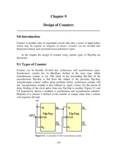
inst.eecs.berkeley.eduG D S I D I G-V DS + + V G S _ NMOS I-V CHARACTERISTIC • Since the transistor is a 3-terminal device, there is no single I-V characteristic. • Note that because of the gate insulator, I G = 0 A. • We typically define the MOS I-V characteristic as I D vs. V DS for a fixed V GS. • 3 modes of operation
Related documents

Chapter 18 Sequential Circuits: Flip-flops and Counters
wps.pearsoned.comDesign a counter with the following repeated binary sequence: 0, 4, 2, 1, 6. Use T flip-flops. Solution: Step 1: Since it is a 3-bit counter, the number of flip-flops required is three. Step 2: Let the type of flip-flops be RS flip-flops. Step 3: Let the three flip-flops be A, B and C. Step 4: The state table is as shown in Table 3.1.
Chapter 9 Design of Counters - Universiti Tunku Abdul Rahman
staff.utar.edu.mylearnt earlier in Chapter 7, the excitation or characteristic table of SR flip-flop, D flip-flip, JK flip-flop, and T flip-flop are shown in Fig. 9.7. and 9.8 respectively. Q t is denotes the output of the present state and Q t+1 denotes the output of next state.

Sequential Circuit Design - University of Pittsburgh
sites.pitt.eduElec 326 14 Sequential Circuit Design Select the Flip-Flop Type The four main types of flip-flops are SR, D, T and JK. The choice of flip-flop type can affect the complexity of the combinational logic in the resulting sequential circuit. Of three common types, the most versatile is the JK, since it can be easily converted into the other two.

SystemVerilog Assertions Design Tricks and SVA Bind Files
www.sunburst-design.comMar 24, 2009 · exceptionally incompetent engineer has coded a very flawed D-flip-flop as shown in Example 1: module dff (output logic q, input d, clk, rst_n); assign q = d; // This is clearly a mistake!! endmodule Example 1 - Incorrectly coded D-flip-flop model To this dff module, let's first add a concurrent assertion with no label, but we will include an

FPGA Logic Cells Comparison - Sharif
ee.sharif.edu• D flip-flop or latch. Fig. 3: A simplified diagram of the Altera ALM 4-input LUT 3-input LUT 3-input LUT 4-input LUT 3-input LUT 3-input LUT Interconnect ... 1-CORE Technologies is a leading Russian electronics design company providing high-quality and cost-effective FPGA and ASIC design services. Address: 24 Radio str., Moscow, Russia, 105005

Modeling Latches and Flip-flops - Xilinx
www.xilinx.comThe D flip-flop can be viewed as a memory cell or a delay line. The active edge in a flip-flop could be rising or falling. The following figure shows rising (also called positive) edge triggered D flip-flop and falling (negative edge) triggered D flip-flop. The positive edge triggered D flip-flop can be modeled using behavioral modeling as ...

Modeling Latches and Flip-flops - Xilinx
www.xilinx.comThe D flip-flop captures the value of the D-input at a definite portion of the clock cycle (such as the rising edge of the clock). That captured value becomes the Q output. At other times, the output Q does not change. The D flip-flop can be viewed as a memory cell or a delay line. The active edge in a flip-flop could be rising or falling.

ICL8038 - MIT
www.mit.eduthat the flip-flop is in a state such that current source #2 is off, and the capacitor is charged with a current I, the voltage across the capacitor rises linearly with time. When this voltage reaches the level of comparator #1 (set at 2/3 of the supply voltage), the flip-flop is triggered, changes states, and releases current source #2.

Hobby Servo Fundamentals - Princeton University
www.princeton.eduflip-flop that toggles the direction the current flows through the motor. The outputs of the flip-flop drive an H-Bridge circuit that handles the high current going through the motor. If you were going to try to build a circuit to take a PWM signal and convert it to a motor position, you'd probably end up with a fairly large circuit.