Transcription of NX2301P 20 V, 2 A P-channel Trench MOSFET - Nexperia
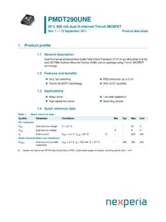
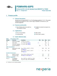
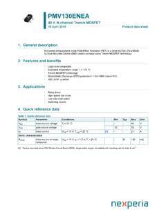
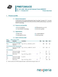
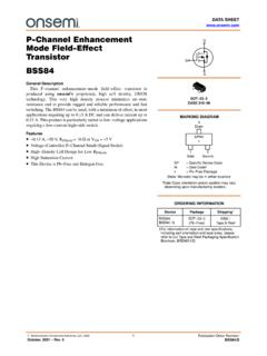
1 NX2301P . 20 V, 2 A P-channel Trench MOSFET . Rev. 1 26 October 2010 Product data sheet 1. Product profile General description P-channel enhancement mode field -Effect Transistor (FET) in a small SOT23 (TO-236AB) Surface-Mounted Device (SMD) plastic package using Trench MOSFET technology. Features and benefits V RDSon rated for Low Voltage Gate Drive Very fast switching Trench MOSFET technology AEC-Q101 qualified Applications Relay driver High-speed line driver High-side loadswitch Switching circuits Quick reference data Table 1. Quick reference data Symbol Parameter Conditions Min Typ Max Unit VDS drain-source voltage Tamb = 25 C - - 20 V. VGS gate-source voltage Tamb = 25 C - - 8 V. ID drain current Tamb = 25 C; [1] - - 2 A.
2 VGS = V. RDSon drain-source on-state Tj = 25 C; [2] - 100 120 m . resistance VGS = V;. ID = 1 A. [1] Device mounted on an FR4 PCB, single-sided copper, tin-plated, mounting pad for drain 6 cm2, t 5 s. [2] Pulse test: tp 300 s; Nexperia NX2301P . 20 V, 2 A P-channel Trench MOSFET . 2. Pinning information Table 2. Pinning Pin Symbol Description Simplified outline Graphic symbol 1 G gate 3 D. 2 S source 3 D drain G. 1 2. S. 017aaa094. 3. Ordering information Table 3. Ordering information Type number Package Name Description Version NX2301P TO-236AB plastic surface-mounted package; 3 leads SOT23. 4. Marking Table 4. Marking codes Type number Marking code[1]. NX2301P MG*. [1] * = placeholder for manufacturing site code 5.
3 Limiting values Table 5. Limiting values In accordance with the Absolute Maximum Rating System (IEC 60134). Symbol Parameter Conditions Min Max Unit VDS drain-source voltage Tamb = 25 C - 20 V. VGS gate-source voltage Tamb = 25 C - 8 V. ID drain current VGS = V [1]. Tamb = 25 C - 2 A. Tamb = 100 C - A. IDM peak drain current Tamb = 25 C; - 6 A. single pulse; tp 10 s NX2301P All information provided in this document is subject to legal disclaimers. Nexperia 2017. All rights reserved Product data sheet Rev. 1 26 October 2010 2 of 16. Nexperia NX2301P . 20 V, 2 A P-channel Trench MOSFET . Table 5. Limiting values continued In accordance with the Absolute Maximum Rating System (IEC 60134). Symbol Parameter Conditions Min Max Unit Ptot total power dissipation Tamb = 25 C [2] - 400 mW.
4 [1] - 710 mW. Tsp = 25 C - W. Tj junction temperature 150 C. Tamb ambient temperature 55 +150 C. Tstg storage temperature 65 +150 C. Source-drain diode IS source current Tamb = 25 C [1] - A. [1] Device mounted on an FR4 PCB, single-sided copper, tin-plated, mounting pad for drain 6 cm2, t 5 s. [2] Device mounted on an FR4 PCB, single-sided copper, tin-plated and standard footprint. 017aaa001 017aaa002. 120 120. Pder Ider (%) (%). 80 80. 40 40. 0 0. 75 25 25 75 125 175 75 25 25 75 125 175. Tamb ( C) Tamb ( C). P tot ID. P der = ------------------------ 100 % I der = -------------------- 100 %. P tot ( 25 C ) I D ( 25 C ). Fig 1. Normalized total power dissipation as a Fig 2. Normalized continuous drain current as a function of ambient temperature function of ambient temperature NX2301P All information provided in this document is subject to legal disclaimers.
5 Nexperia 2017. All rights reserved Product data sheet Rev. 1 26 October 2010 3 of 16. Nexperia NX2301P . 20 V, 2 A P-channel Trench MOSFET . 017aaa095. 10. Limit RDSon = VDS/ID. ID. (A) (1). 1. (2). (3). 10 1 (4). (5). 10 2. 10 1 1 10 102. VDS (V). IDM = single pulse (1) tp = 1 ms (2) tp = 10 ms (3) DC; Tsp = 25 C. (4) tp = 100 ms (5) DC; Tamb = 25 C; drain mounting pad 6 cm2. Fig 3. Safe operating area; junction to ambient; continuous and peak drain currents as a function of drain-source voltage 6. Thermal characteristics Table 6. Thermal characteristics Symbol Parameter Conditions Min Typ Max Unit Rth(j-a) thermal resistance from in free air [1] - - 315 K/W. junction to ambient [2] - - 175 K/W.
6 Rth(j-sp) thermal resistance from - - 45 K/W. junction to solder point [1] Device mounted on an FR4 PCB, single-sided copper, tin-plated and standard footprint. [2] Device mounted on an FR4 PCB, single-sided copper, tin-plated, mounting pad for drain 6 cm2, t 5 s. NX2301P All information provided in this document is subject to legal disclaimers. Nexperia 2017. All rights reserved Product data sheet Rev. 1 26 October 2010 4 of 16. Nexperia NX2301P . 20 V, 2 A P-channel Trench MOSFET . 017aaa096. 103. Zth(j-a) duty cycle = 1. (K/W). 102 10 0. 1. 10 3 10 2 10 1 1 10 102 103. tp (s). FR4 PCB, standard footprint Fig 4. Transient thermal impedance from junction to ambient as a function of pulse duration; typical values 017aaa097.
7 103. Zth(j-a). (K/W) duty cycle = 1. 102 10. 0 1. 10 3 10 2 10 1 1 10 102 103. tp (s). FR4 PCB, mounting pad for drain 6 cm2. Fig 5. Transient thermal impedance from junction to ambient as a function of pulse duration; typical values NX2301P All information provided in this document is subject to legal disclaimers. Nexperia 2017. All rights reserved Product data sheet Rev. 1 26 October 2010 5 of 16. Nexperia NX2301P . 20 V, 2 A P-channel Trench MOSFET . 7. Characteristics Table 7. Characteristics Tj = 25 C unless otherwise specified. Symbol Parameter Conditions Min Typ Max Unit Static characteristics V(BR)DSS drain-source breakdown ID = 250 A; VGS = 0 V 20 - - V. voltage VGS(th) gate-source threshold ID = 250 A; VDS = VGS V.
8 Voltage IDSS drain leakage current VDS = 20 V; VGS = 0 V - - 1 A. IGSS gate leakage current VGS = 8 V; VDS = 0 V - - 100 nA. RDSon drain-source on-state [1]. resistance VGS = V; ID = 1 A. Tj = 25 C 100 120 m . Tj = 150 C - 180 m . VGS = V; ID = 1 A - 155 190 m . VGS = V; - 210 270 m . ID = A. gfs forward VDS = 5 V; ID = 2 A [1] - - S. transconductance Dynamic characteristics QG(tot) total gate charge ID = A; VDS = 6 V; - 6 nC. QGS gate-source charge VGS = V - - nC. QGD gate-drain charge - - nC. Ciss input capacitance VGS = 0 V; VDS = 6 V; - 380 - pF. Coss output capacitance f = 1 MHz - 135 - pF. Crss reverse transfer - 115 - pF. capacitance td(on) turn-on delay time VDD = 6 V; - 7 - ns tr rise time RL = 6 ; - 15 - ns VGS = V.
9 Td(off) turn-off delay time RG = 6 - 50 - ns tf fall time - 25 - ns Source-drain diode VSD source-drain voltage IS = 1 A; VGS = 0 V [1] - V. [1] Pulse test: tp 300 s; NX2301P All information provided in this document is subject to legal disclaimers. Nexperia 2017. All rights reserved Product data sheet Rev. 1 26 October 2010 6 of 16. Nexperia NX2301P . 20 V, 2 A P-channel Trench MOSFET . 017aaa098 017aaa099. 10 3. VGS = V V. ID ID. (A) (A). 10 4. (1) (2) (3). V. 10 5. V. V. 10 6. VDS (V) VGS (V). Tamb = 25 C Tamb = 25 C; VDS = 10 V. (1) minimum values (2) typical values (3) maximum values Fig 6. Output characteristics: drain current as a Fig 7. Sub-threshold drain current as a function of function of drain-source voltage; typical gate-source voltage values 017aaa100 017aaa101.
10 RDSon RDson ( ) ( ). (1) (2). (3). (1). (4) (2). ID (A) VGS (V). Tamb = 25 C ID = 2 A. (1) VGS = V (1) Tamb = 125 C. (2) VGS = V (2) Tamb = 25 C. (3) VGS = V. (4) VGS = V. Fig 8. Drain-source on-state resistance as a function Fig 9. Drain-source on-state resistance as a function of drain current; typical values of gate-source voltage; typical values NX2301P All information provided in this document is subject to legal disclaimers. Nexperia 2017. All rights reserved Product data sheet Rev. 1 26 October 2010 7 of 16. Nexperia NX2301P . 20 V, 2 A P-channel Trench MOSFET . 017aaa102 017aaa103. ID a (A). (1) (2). 60 0 60 120 180. VGS (V) Tamb ( C). VDS > ID RDSon R DSon (1) Tamb = 150 C a = ----------------------------- R DSon ( 25 C ).