Transcription of MC74HC14A - Hex Schmitt-Trigger Inverter
1 Semiconductor Components Industries, LLC, 2014 August, 2014 Rev. 141 Publication Order Number: MC74HC14A /DMC74HC14 AHex schmitt -TriggerInverterHigh Performance Silicon Gate CMOSThe MC74HC14A is identical in pinout to the LS14, LS04 and theHC04. The device inputs are compatible with Standard CMOS outputs; with pullup resistors, they are compatible with HC14A is useful to square up slow input rise and fall to hysteresis voltage of the schmitt trigger, the HC14A findsapplications in noisy Output Drive Capability: 10 LSTTL Loads Outputs Directly Interface to CMOS, NMOS and TTL Operating Voltage Range: to V Low Input Current: mA High Noise Immunity Characteristic of CMOS Devices In Compliance With the JEDEC Standard No.
2 A Requirements Chip Complexity: 60 FETs or 15 Equivalent Gates NLV Prefix for Automotive and Other Applications RequiringUnique Site and Control Change Requirements; AEC Q100 Qualified and PPAP Capable These Devices are Pb Free, Halogen Free/BFR Free and are RoHSCompliantLOGIC DIAGRAMY1A1A2A3A4A5A6Y2Y3Y4Y5Y6135911132 4681012Y = APin 14 = VCCPin 7 = detailed ordering and shipping information in the packagedimensions section on page 5 of this data INFORMATIONMARKING DIAGRAMSA= Assembly LocationL, WL= Wafer LotY, YY= YearW, WW= Work WeekG or G= Pb Free PackageTSSOP 14DT SUFFIXCASE 948 GSOIC 14 NBD SUFFIXCASE 751 AHC14 AGAWLYWW114HC14 AALYWGG114(Note.)
3 Microdot may be in either location)TSSOP 14 SOIC 14 NBPIN ASSIGNMENT1314121110982134567 VCCA6Y6A5Y5A4Y4A1Y1A2Y2A3Y3 GND14 Lead (Top View)LHFUNCTION TABLEI nputsOutputsAHLYMC74HC14 RATINGSS ymbolParameterValueUnitVCCDC Supply Voltage (Referenced to GND) to + Input Voltage (Referenced to GND) to VCC + Output Voltage (Referenced to GND) to VCC + Input Current, per Pin 20mAIoutDC Output Current, per Pin 25mAICCDC Supply Current, VCC and GND Pins 50mAPDP ower Dissipation in Still Air,SOIC Package TSSOP Package 500450mWTstgStorage Temperature Range 65 to +150_CTLLead Temperature, 1 mm from Case for 10 SecondsPlastic DIP, SOIC or TSSOP Package260_CStresses exceeding those listed in the Maximum Ratings table may damage the device.
4 If anyof these limits are exceeded, device functionality should not be assumed, damage may occurand reliability may be affected. Derating: SOIC Package: 7 mW/_C from 65_ to 125_CTSSOP Package: mW/_C from 65_ to 125_CRECOMMENDED OPERATING CONDITIONSS ymbolParameterMinMaxUnitVCCDC Supply Voltage (Referenced to GND) , VoutDC Input Voltage, Output Voltage (Referenced to GND)0 VCCVTAO perating Temperature Range, All Package Types 55+125_Ctr, tfInput Rise/Fall TimeVCC = V(Figure 1)VCC = VVCC = V000No Limit*No Limit*No Limit*nsFunctional operation above the stresses listed in the Recommended Operating Ranges is not implied.
5 Extended exposure to stresses beyondthe Recommended Operating Ranges limits may affect device reliability.*When Vin = 50% VCC, ICC > 1mAThis device contains protectioncircuitry to guard against damagedue to high static voltages or electricfields. However, precautions mustbe taken to avoid applications of anyvoltage higher than maximum ratedvoltages to this high impedancecircuit. For proper operation, Vin andVout should be constrained to therange GND v (Vin or Vout) v inputs must always betied to an appropriate logic voltagelevel ( , either GND or VCC).
6 Unused outputs must be left CHARACTERISTICS (Voltages Referenced to GND)VCCVG uaranteed LimitSymbolParameterCondition 55 to 25 C 85 C 125 CUnitVT+ maxMaximum Positive Going InputThreshold Voltage(Figure 3)Vout = |Iout| + minMinimum Positive Going InputThreshold Voltage(Figure 3)Vout = |Iout| maxMaximum Negative Going InputThreshold Voltage(Figure 3)Vout = VCC |Iout| minMinimum Negative Going InputThreshold Voltage(Figure 3)Vout = VCC |Iout| (Note 1)Maximum Hysteresis Voltage(Figure 3)Vout = or VCC |Iout| (Note 1)Minimum Hysteresis Voltage(Figure 3)Vout = or VCC |Iout| High Level OutputVoltageVin VT min|Iout| VT min|Iout| |Iout| |Iout| Low Level OutputVoltageVin VT+ max|Iout| VT+ max|Iout| |Iout| |Iout| Input LeakageCurrentVin = VCC or Quiescent SupplyCurrent (per Package)Vin = VCC or GNDIout = VHmin > (VT+ min) (VT max); VHmax = (VT+ max) (VT min).
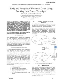
7 AC CHARACTERISTICS (CL = 50pF, Input tr = tf = 6ns)VCCVG uaranteed LimitSymbolParameter 55 to 25 C 85 C 125 CUnittPLH,tPHLM aximum Propagation Delay, Input A or B to Output Y(Figures 1 and 2) ,tTHLM aximum Output Transition Time, Any Output(Figures 1 and 2) Input Capacitance101010pFCPDP ower Dissipation Capacitance (Per Inverter )*Typical @ 25 C, VCC = VpF22* Used to determine the no load dynamic power consumption: PD = CPD VCC2f + ICC 1. Switching WaveformsGNDVCCOUTPUT YINPUT ACL**Includes all probe and jig capacitanceTESTPOINT90%50%10%tTLHDEVICEU NDERTESTOUTPUTF igure 2.
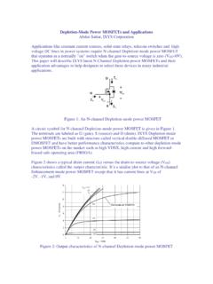
8 Test CircuittTHL90%50%10%tPLHtPHLtftrVHtypFig ure 3. Typical Input Threshold, VT+, VT versus Power Supply VoltageVCC, POWER SUPPLY VOLTAGE (VOLTS)234561234VT, TYPICAL INPUT THRESHOLD VOLTAGE (VOLTS)VHtyp = (VT+ typ) - (VT- typ)(VT+)(VT-)MC74HC14 4. Typical schmitt Trigger ApplicationsVHVinVoutVCCVT+VT-GNDVOHVOLV HVinVoutVCCVT+VT-GNDVOHVOL(a) A Schmitt-Trigger Squares Up Inputs With Slow Rise and Fall Times(b) A Schmitt-Trigger Offers Maximum Noise ImmunityYAORDERING INFORMATIOND evicePackageShipping MC74HC14 ADGSOIC 14 NB(Pb Free)55 Units / RailMC74HC14 ADR2 GSOIC 14 NB(Pb Free)2500 / Tape & ReelMC74HC14 ADTGTSSOP 14(Pb Free)96 Units / RailMC74HC14 ADTR2 GTSSOP 14(Pb Free)2500 / Tape & ReelNLV74HC14 ADG*SOIC 14 NB(Pb Free)55 Units / RailNLV74HC14 ADR2G*SOIC 14 NB(Pb Free)
9 2500 / Tape & ReelNLV74HC14 ADTG*TSSOP 14(Pb Free)96 Units / RailNLV74HC14 ADTR2G*TSSOP 14(Pb Free)2500 / Tape & Reel For information on tape and reel specifications, including part orientation and tape sizes, please refer to our Tape and Reel PackagingSpecifications Brochure, BRD8011/D.*NLV Prefix for Automotive and Other Applications Requiring Unique Site and Control Change Requirements; AEC Q100 Qualified and PPAPC apableMC74HC14 DIMENSIONSTSSOP 14 CASE 948 GISSUE BSCM0 8 0 8 NOTES:1.
10 DIMENSIONING AND TOLERANCING PERANSI , CONTROLLING DIMENSION: DIMENSION A DOES NOT INCLUDE MOLDFLASH, PROTRUSIONS OR GATE FLASH OR GATE BURRS SHALL NOTEXCEED ( ) PER DIMENSION B DOES NOT INCLUDEINTERLEAD FLASH OR FLASH OR PROTRUSION SHALLNOT EXCEED ( ) PER DIMENSION K DOES NOT INCLUDEDAMBAR PROTRUSION. ALLOWABLEDAMBAR PROTRUSION SHALL BE ( ) TOTAL IN EXCESS OF THE KDIMENSION AT MAXIMUM TERMINAL NUMBERS ARE SHOWN FORREFERENCE DIMENSION A AND B ARE TO BEDETERMINED AT DATUM PLANE W . ( )T2 ( )VSTL U ( ) T SECTION N NDETAIL EJJ1KK1 DETAIL EFM W ( )81471 PIN ( )T V 14X : MILLIMETERS1 PITCHSOLDERING FOOTPRINT**For additional information on our Pb Free strategy and solderingdetails, please download the ON Semiconductor Soldering andMounting Techniques Reference Manual, DIMENSIONSSOIC 14 NBCASE 751A 03 ISSUE KNOTES:1.