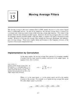
Transcription of AND9313 - AX5043 Use as Analog FM Transceiver
1 AND9313 /D. AX5043 Use as Analog FM. Transceiver Introduction This application note describes how to use the AX5043 as an Analog FM half duplex Transceiver . A modified AX RadioLAB project, ax5043_analog_FM_demo, is used APPLICATION NOTE. to demonstrate FM operation. The AX5043_analog_FM_demo Project The default configuration is for 200 kHz wideband The project is a (broadcast) FM. For narrow band FM the following changes modified AX project. The SLAVE should be made: The RX bandwidth should be adjusted firmware demonstrates Analog FM receive, whereas using AX RadioLAB. The TX deviation should be adjusted MASTER firmware demonstrates Analog FM transmit. by changing AX5043_FSKDEV0 in AX RadioLAB and the AXRadioV2 API provide a basic according to the formula in Transmit side/Software setup, allowing to check for the AX5043 IC, to set some configuration section.
2 General parameters ( carrier frequency) and to range the The following tables list those input parameters of PLL. AX RadioLAB which are relevant here and the derived AX5043 registers relevant for FM operation. Table 1. Parameter Panel Comment Ref Osc Config Pin Configuration A TCXO should be used for narrow band FM (25 kHz channels). An XTAL is sufficient for common FM radio reception. PA Config Pin Configuration Single ended or differential VCO Config Pin Configuration Internal or external L, depending of carrier frequency. Carrier frequency PHY. RFDIV PHY Depending of carrier frequency Symbol Rate PHY AX5043_RXDATARATE is computed from this parameter. In FM RX mode this de- termines the rate at which the baseband signal is sampled.
3 Typically 100 kS/s. Channel Spacing PHY. Fxtal PHY. XTALCAP PHY. Transmit Power PHY. RX Bandwidth PHY. Semiconductor Components Industries, LLC, 2016 1 Publication Order Number: July, 2016 - Rev. 3 AND9313 /D. AND9313 /D. Table 2. AX5043_TMGRXOFFSACQ. Register AX5043_RSSIREFERENCE. AX5043_FREQA3 AX5043_0xF10. AX5043_FREQA2 AX5043_0xF11. AX5043_FREQA1 AX5043_0xF1C. AX5043_FREQA0 AX5043_0xF21. AX5043_DECIMATION AX5043_0xF22. AX5043_RXDATARATE2 AX5043_0xF23. AX5043_RXDATARATE1 AX5043_0xF26. AX5043_RXDATARATE0 AX5043_0xF34. AX5043_AGCGAIN0 AX5043_0xF35. AX5043_AGCTARGET0 AX5043_0xF44. AX5043_PHASEGAIN0 AX5043_PLLLOOP. AX5043_AMPLITUDEGAIN0 AX5043_PLLCPI. AX5043_FREQDEV10 AX5043_PLLVCODIV.
4 AX5043_FREQDEV00 AX5043_PLLVCOI. AX5043_BBOFFSRES0 AX5043_XTALCAP. AX5043_MODCFGF AX5043_0xF00. AX5043_MODCFGA AX5043_REF. AX5043_TXPWRCOEFFB1 AX5043_0xF18. AX5043_TXPWRCOEFFB0. AX5043_PLLRNGCLK Further AX5043 register settings relevant for Analog FM. AX5043_BBTUNE operation are hard coded in the COMMON/set_fm_tx() and COMMON/set_fm_rx() routines. They are described in the AX5043_BBOFFSCAP. further sections of this document. AX5043_TMGRXBOOST AX5043 registers related to preamble matching and the AX5043_TMGRXSETTLE packet engine are irrelevant for Analog FM operation. 2. AND9313 /D. Receive Side Hardware Setup Pin: PWRAMP or ANTSEL. AX5043 Low pass filter Amplifier Figure 1.
5 The AX5043 features a bitstream DAC, which can output 4. Bit timing recovery should be disabled by setting a demodulated baseband signal. The output can be AX5043_TIMEGAIN0, AX5043_DRGAIN0 and configured to be on pin ANTSEL or PWRAMP. On the AX5043_MAXDROFFSET to 0. ON Semiconductor DVK2b modules PWRAMP is used. To 5. The AFC loop controlled by convert the bitstream into an audio signal a low pass filter AX5043_FREQGAINA and and an amplifier are required. The low pass filter on the AX5043_FREQGAINB (TRKFREQ) us used as DVK2b modules is first order with a cutoff frequency of an FM demodulator. The AFC loop controlled by kHz. For better audio quality a higher order filter is AX5043_FREQGAINC and required.
6 AX5043_FREQGAIND (TRKRFFREQ) is used for tracking static frequency offsets. Software Configuration AX5043_FREQUENCYLEAK > 0 prevents the Analog FM mode is selected by setting demodulator loop from tracking static frequency AX5043_MODULATION = 0x0B . offsets. The following points have to be considered: 6. In the formulas for AX5043_IFFREQ, 1. RX bandwidth and IF configuration function as in AX5043_DECIMATION and other receive modes. AX5043_RXDATARATE listed in the AX5043 . 2. The formula for AX5043_RXDATARATE is the Programming Manual, the quantity fxtal should be same as for digital receive modes, except that replaced by fxtal/2^(ADCCLKMUX), where BITRATE is replaced by fSR, the sampling rate of ADCLKMUX = 0xF35[1:0].
7 The baseband signal. 3. AX5043_RXPARAMSETS = 0x00 ensures that The following table shows register settings for FM radio the RX parameter set 0 is used at all times. reception with a 16 MHz reference. Therefore receiver parameter sets 1, 2 and 3 are not used. Registers related to preamble matching and the packet engine are not used. Table 3. Register Value Calculation / Comment AX5043_MODULATION 0x0B Analog FM. AX5043_IFFREQ 0x0666 25 kHz (f_xtal = 16 MHz). AX5043_RXPARAMSETS 0x00 only use receiver parameter set 0. AX5043_TIMEGAIN0 0x00 disable bit timing recovery, which would only add jitter AX5043_DRGAIN0 0x00 off AX5043_MAXDROFFSET 0x000000 off AX5043_MAXRFOFFSET2 0x80 CCCC track at LO1, max 50 kHz @ f_xtal = 16 MHz AX5043_FREQUENCYGAINA0 0x0F off AX5043_FREQUENCYGAINB0 0x02 bandwidth of inner AFC loop used for FM demodulation.
8 F_3dB = *BR. This is the fastest setting available AX5043_FREQUENCYGAINC0 0x1F off AX5043_FREQUENCYGAIND0 0x08 bandwidth of outer AFC loop (tracking frequency mismatch), 78 Hz @ BR = 100 kbps, f_xtal = 16 MHz 3. AND9313 /D. Table 3. Register Value Calculation / Comment AX5043_FREQUENCYLEAK 0x04 FREQUENCYGAINB0 + 2, prevents the demodulator AFC loop from tracking static frequency offsets AX5043_DACCONFIG 0x03 output TRKFREQUENCY (= demodulated signal) on DAC. AX5043_DACVALUE1 0x00. AX5043_DACVALUE0 0x0c DACSHIFT = 12 bit. This gives maximum volume, downshifting further gives smaller volume AX5043_PINFUNCPWRAMP 0x05 Use PWRAMP pin as DAC output AX5043_PWRMODE 0x09 FULL RX.
9 With this settings the AX5043 will output a FM radio standard high impedance ear piece directly to the pins on the channel at the set frequency. It is possible to connect a DVK2b module to listen to the radio. Transmit Side Hardware Setup Low pass Microphone filter Amplifier Pins GPADC1 & GPADC2. AX5043 . Figure 2. The baseband (audio) signal should be applied A microphone signal should be amplified to 500 mVpp differentially to pins GPADC1 and GPADC2 (Pins 25 and differential signal. 26) when using the standalone AX5043 . The baseband Software Configuration (audio) signal should be applied differentially to pins TST2. Analog FM mode is selected by setting and TST1 (Pins 27 and 28) when using the SoC.
10 AX5043_MODULATION = 0x0B. AX8052F143. The register FSKDEV has a special meaning when FM. The two single ended GPADC input signals should swing modulation is selected. It defines the conditioning of the around the common mode voltage of 800 mV. The ADC signal prior modulation. maximum common mode range is 100 mV. The maximum AX5043_GPADCPERIOD controls the rate at which the differential input signal is 1 Vpp. Thus the maximum Analog baseband signal is sampled. AX5043_TXRATE has negative input signal is ((800 mV 250 mV) (800 mV +. no meaning in FM mode. 250 mV)) = 500 mV, the maximum positive input signal is ((800 mV + 250 mV) (800 mV 250 mV)) = 500 mV. The single ended input impedance of each GPADC pin is 50 kW.