Transcription of LTC1144 - Switched-Capacitor Wide Input Range Voltage ...
1 LTC 114411144faFor more information applicaTion FeaTuresDescripTionSwitched-Capacitor Wide Input Range Voltage Converter with ShutdownThe LT C 1144 is a monolithic CMOS Switched-Capacitor Voltage converter. It performs supply Voltage conversion from positive to negative from an Input Range of 2V to 18V, resulting in complementary output voltages of 2V to 18V. Only two noncritical external capacitors are needed for the charge pump and charge reservoir converter has an internal oscillator that can be overdriven by an external clock or slowed down when connected to a capacitor. The oscillator runs at a 10kHz frequency when unloaded. A higher frequency outside the audio band can also be obtained if the Boost Pin is tied to V+.
2 The SHDN pin reduces supply current to 8 A and can be used to save power when the converter is not in LTC1144 contains an internal oscillator, divide-by- two, Voltage level shifter, and four power mosfets . A special logic circuit will prevent the power N-channel switch substrate from turning Wide Operating Supply Voltage Range : 2V to 18Vn Boost Pin (Pin 1) for Higher Switching Frequencyn Simple Conversion of 15V to 15V Supplyn Low Output Resistance: 120 Maximumn Power Shutdown to 8 A with SHDN Pinn Open Circuit Voltage Conversion Efficiency: Typicaln Power Conversion Efficiency: 93% Typicaln Easy to Usen Conversion of 15V to 15V Suppliesn Inexpensive Negative Suppliesn Data Acquisition Systemsn High Voltage Upgrade to LTC1044 or 7660n Voltage Division and Multiplicationsn Automotive Applicationsn Battery Systems with Wall Adapter/ChargerL, LT, LT C, LT M, Linear Technology and the Linear logo are registered trademarks of Linear Technology Corporation.
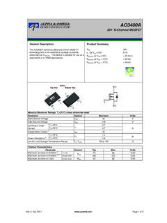
3 All other trademarks are the property of their respective Voltage vs Load Current, V+ = 15 VGenerating 15V from 15V12348765 BOOSTCAP+GNDCAP V+OSCSHDNVOUT++10 F 15V OUTPUT15V INPUTLTC114410 F1144 TA01 LOAD CURRENT (mA)010 OUTPUT Voltage (V) 15 14 13 12 11 10401144 TA02203050 ROUT = 56 TA = 25 CLTC 114421144faFor more information MaxiMuM raTingsSupply Voltage (V+) (Tr ansi en t) ..20 VSupply Voltage (V+) (Operating) .. 18 VInput Voltage on Pins 1, 6, 7 (Note 2) .. < VIN < (V+) + Short-Circuit Duration V+ 10V .. Indefinite V+ 15V .. 30 sec V+ 20V .. Not ProtectedPower Dissipation .. 500mWOperating Temper atur e Range LTC114 C to 70 C LTC114 4I .. 40 C to 85 CStorage Temper atur e Range .
4 65 C to 150 CLead Temper atur e (Soldering, 10 sec) ..300 C(Note 1)orDer inForMaTionLEAD FREE FINISHTAPE AND REELPART MARKINGPACKAGE DESCRIPTIONTEMPERATURE RANGELTC1144CN8#PBFLTC1144CN8#TRPBFLTC11 44CN88-Lead Plastic DIP0 C to 70 CLTC1144IN8#PBFLTC1144IN8#TRPBFLTC1144IN 88-Lead Plastic DIP 40 C to 85 CLTC1144CS8#PBFLTC1144CS8#TRPBF11448-Lea d Plastic SOIC0 C to 70 CLTC1144IS8#PBFLTC1144IS8#TRPBF1144I8-Le ad Plastic SOIC 40 C to 85 CConsult LT C Marketing for parts specified with wider operating temperature ranges. Consult LT C Marketing for information on nonstandard lead based finish more information on lead free part marking, go to: For more information on tape and reel specifications, go to: VIEWBOOSTCAP+GNDCAP V+OSCSHDNVOUTN8 PACKAGE8-LEAD PLASTIC DIP TJMAX = 110 C, JA = 100 C/WTOP VIEW12348765 BOOSTCAP+GNDCAP V+OSCSHDNVOUTS8 PACKAGE8-LEAD PLASTIC SOIC TJMAX = 110 C, JA = 130 C/Wpin conFiguraTionLTC 114431144faFor more information characTerisTicsNote 1: Stresses beyond those listed under Absolute Maximum Ratings may cause permanent damage to the device.
5 Exposure to any Absolute Maximum Rating condition for extended periods may affect device reliability and 2: Connecting any Input terminal to voltages greater than V+ or less than ground may cause destructive latch-up. It is recommended that no inputs from sources operating from external supplies be applied prior to power-up of the 3: fOSC is tested with COSC = 100pF to minimize the effects of test fixture capacitance loading. The 0pF frequency is correlated to this 100pF test point, and is intended to simulate the capacitance at pin 7 when the device is plugged into a test socket and no external capacitor is Voltage RangeRL = 10kl218218 VISS upply CurrentRL = , Pins 1, 6 No Connection, fOSC = 10kHz mASHDN = 0V, RL = , Pins 1, 7 No + = 5V, RL = , Pins 1, 6 No Connection, fOSC = 4kHz mAV+ = 5V, SHDN = 0V, RL = , Pins 1, 7 No ResistanceV+ = 15V, IL = 20mA at 10kHz l56100 12056100 140 V+ = 5V, IL = 3mA at 4kHzl9025090300 fOSCO scillator FrequencyV+ = 15V (Note 3)
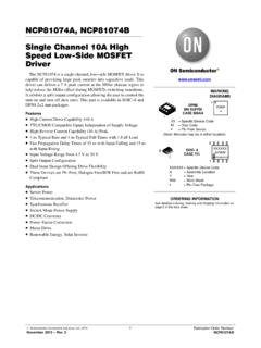
6 V+ = 5V10 410 4kHz kHzPower EfficiencyRL = 2k at 10kHzl90939093% Voltage Conversion EfficiencyRL = Sink or Source Current V+ = 5V (VOSC = 0V to 5V) V+ = 15V (VOSC = 0V to 15V) 4 A A The l denotes the specifications which apply over the full operating temperature Range ,V+ = 15V, COSC = 0pF, Test Circuit Figure 1, otherwise specifications are at TA = 25 114441144faFor more information perForMance characTerisTicsOscillator Frequency as a Function of COSCO scillator Frequency vs TemperatureOutput Voltage vs Load CurrentOutput Voltage vs Load CurrentSupply Current as a Function of Oscillator FrequencyPower Conversion Efficiency and Supply Current vs Load CurrentOutput Resistance vs Supply VoltageOutput Resistance vs TemperatureOscillator Frequency vs Supply VoltageSUPPLY Voltage (V)20 OUTPUT RESISTANCE ( )
7 501001502006101418 LTC1144 TPC01250300481216TA = 25 CEXTERNAL CAPACITANCE (PIN 7 TO GND), COSC (pF)1 OSCILLATOR FREQUENCY (kHz)11010000 LTC1144 = 25 CV+ = 15 VBOOST = OPEN OR GROUNDBOOST = V+LOAD CURRENT (mA)0 5 OUTPUT Voltage (V) 4 3 2 105101520 LTC1144 TPC072530TA = 25 CV+ = 5VC1 = C2 = 10 FBOOST = OPENROUT = 90 TEMPERATURE ( C) 55 OUTPUT RESISTANCE ( )1001201402575 LTC1144 TPC028060 250501001254020V+ = 5 VIL = 3mAV+ = 15 VIL = 20mATEMPERATURE ( C) 55 25 OSCILLATOR FREQUENCY (kHz)1010010000255075100125 LTC1144 TPC051 BOOST = V+BOOST = OPEN OR GROUNDTA = 25 CV+ = 15 VOSCILLATOR FREQUENCY (kHz) CURRENT ( A)1001000100 LTC1144 = 25 CC1 = C2 = 10 FV+ = 15VV+ = 5 VSUPPLY Voltage (V)2 OSCILLATOR FREQUENCY (kHz)1010010006101448121618 LTC1144 TPC031TA = 25 CCOSC = 0 BOOST = V+BOOST = OPEN OR GROUNDLOAD CURRENT (mA)0 15 OUTPUT Voltage (V) 10 5010203040 LTC1144 TPC065060TA = 25 CV+ = 15VC1 = C2 = 10 FBOOST = OPENROUT = 56 LOAD CURRENT (mA)0 POWER CONVERSION EFFICIENCY (%)SUPPLY CURRENT (mA)608010040 LTC1144 TPC094020060801004020010203050 PEFFISTA = 25 CV+ = 15VC1 = C2 = 10 FBOOST = OPEN(SEE TEST CIRCUIT)
8 LTC 114451144faFor more information perForMance characTerisTicsRipple Voltage vs Load CurrentOutput Voltage vs Load CurrentOutput Voltage vs Load CurrentPower Conversion Efficiency and Supply Current vs Load CurrentPower Conversion Efficiency vs Oscillator FrequencyOutput Resistance vs Oscillator FrequencyBoost (Pin 1): This pin will raise the oscillator frequency by a factor of 10 if tied + (Pin 2): Positive Terminal for Pump (Pin 3): Ground (Pin 4): Negative Terminal for Pump (Pin 5): Output of the (Pin 6): Shutdown Pin. Tie to V+ pin or leave float-ing for normal operation. Tie to ground when in shutdown (Pin 7): Oscillator Input Pin. This pin can be overdriven with an external clock or can be slowed down by connect-ing an external capacitor between this pin and + (Pin 8).
9 Input CURRENT (mA)0 POWER CONVERSION EFFICIENCY (%)SUPPLY CURRENT (mA)608010016 LTC1144 TPC104020030405020100481220 PEFFISTA = 25 CV+ = 5VC1 = C2 = 10 FBOOST = OPEN(SEE TEST CIRCUIT)LOAD CURRENT (mA) Voltage (mV)50010001 F1 F10 F10 FV+ = 5 VTA = 25 CC1 = C2 BOOST = 5 VBOOST = FOSCILLATOR FREQUENCY (kHz) CONVERSION EFFICIENCY (%)9095100110100 LTC1144 TPC11858075TA = 25 C, V+ = 15 VBOOST = OPENIL = 20mAIL = 3mA1 F1 F10 F10 F100 F100 FLOAD CURRENT (mA) 4 OUTPUT Voltage (V) 3 2 G14 F 10 F10 F1 F1 FV+ = 5 VTA = 25 CC1 = C2 BOOST = 5 VBOOST = OPENOSCILLATOR FREQUENCY (kHz) RESISTANCE ( )20003000110100 LTC1144 TPC1 10001 F10 F100 FTA = 25 CV+ = 15 VLOAD CURRENT (mA) 10 OUTPUT Voltage (V) TPC15 + = 15 VTA = 25 CC1 = C2 BOOST = F1 F1 F10 F10 FBOOST = OPENpin FuncTionsLTC 114461144faFor more information circuiTapplicaTions inForMaTion12348765++C110 FC210 FISVOUTV+15 VILRLEXTERNALOSCILLATORCOSC1144 F01 LTC1144 Figure 2.
10 Switched-Capacitor Building BlockFigure 3. Switched-Capacitor Equivalent CircuitFigure 4. LTC1144 Switched-Capacitor Voltage Converter Block DiagramTheory of OperationTo understand the theory of operation of the LTC1144 , a review of a basic Switched-Capacitor building block is Figure 2, when the switch is in the left position, capaci-tor C1 will charge to Voltage V1. The total charge on C1 will be q1 = C1V1. The switch then moves to the right, discharging C1 to Voltage V2. After this discharge time, the charge on C1 is q2 = C1V2. Note that charge has been transferred from the source V1 to the output V2. The amount of charge transferred is: q = q1 q2 = C1(V1 V2)If the switch is cycled f times per second, the charge transfer per unit time ( , current) is: I = f q = f C1(V1 V2)Rewriting in terms of Voltage and impedance equivalence, I=V1 V21f C1 =V1 V2 REQUIVA new variable REQUIV has been defined such that V2 RLC2C1V1f1144 F02V2 RLREQUIVC2V11144 F03 REQUIV =1f C1 REQUIV = 1/(f C1).